A High-Pass Filter. One application of L-R-C series circuits is to high-pass or low-pass filters, which filter out cither the low- or high-frequency components of a signal. A high-pass filter is shown in Fig. P31.47 , where the output voltage is taken across the L-R combination. (The L-R combination represents an inductive coil that also has resistance due to the large length of wire in the coil.) Derive an expression for V out / V s , the ratio of the output and source voltage amplitudes, as a function of the angular frequency ω of the source. Show that when ω is small, this ratio is proportional to ω and thus is small, and show that the ratio approaches unity in the limit of large frequency. Figure P31.47
A High-Pass Filter. One application of L-R-C series circuits is to high-pass or low-pass filters, which filter out cither the low- or high-frequency components of a signal. A high-pass filter is shown in Fig. P31.47 , where the output voltage is taken across the L-R combination. (The L-R combination represents an inductive coil that also has resistance due to the large length of wire in the coil.) Derive an expression for V out / V s , the ratio of the output and source voltage amplitudes, as a function of the angular frequency ω of the source. Show that when ω is small, this ratio is proportional to ω and thus is small, and show that the ratio approaches unity in the limit of large frequency. Figure P31.47
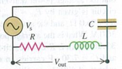
A High-Pass Filter. One application of L-R-C series circuits is to high-pass or low-pass filters, which filter out cither the low- or high-frequency components of a signal. A high-pass filter is shown in Fig. P31.47, where the output voltage is taken across the L-R combination. (The L-R combination represents an inductive coil that also has resistance due to the large length of wire in the coil.) Derive an expression for Vout/Vs, the ratio of the output and source voltage amplitudes, as a function of the angular frequency ω of the source. Show that when ω is small, this ratio is proportional to ω and thus is small, and show that the ratio approaches unity in the limit of large frequency.
In an oscillating LC circuit in which C = 4.00 mF, the maximum potential difference across the capacitor during the oscillations is 1.50 V and the maximum current through the inductor is 50.0 mA.What are (a) the inductance L and (b) the frequency of the oscillations? (c) How much time is required for the charge on the capacitor to rise from zero to its maximum value?
In an oscillating LC circuit, L = 25.0 mH and C = 7.80 mF. At time t 0 the current is 9.20 mA, the charge on the capacitor is 3.80 mC, and the capacitor is charging.What are (a) the total energy in the circuit, (b) the maximum charge on the capacitor, and (c) the maximum current? (d) If the charge on the capacitor is given by q = Q cos(vt + f), what is the phase angle f? (e) Suppose the data are the same, except that the capacitor is discharging at t = 0.What then is f?
1. What is the impedance of a series L-R-C circuit with ? = 10 [mH], ? = 0.1 [kΩ], ? = 1.0 [?F] and ? = 104 rad/s?
A. 0.1 [kΩ]
B. 1 [kΩ]
C. 10 [kΩ]
D. 100 [kΩ]
2. A 25.0 [cm] rod moves 5.00 [m/s] and is immersed in a magnetic field with strength of 0.50 [T]. The length, velocity of the rod, and the magnetic field are all mutually perpendicular. What is the potential difference across the ends of the rod?
A. 0.313 [V]
B. 0.625 [V]
C. 31.3 [V]
D. 62.5 [V]
Chapter 31 Solutions
University Physics with Modern Physics (14th Edition)
Need a deep-dive on the concept behind this application? Look no further. Learn more about this topic, physics and related others by exploring similar questions and additional content below.


 Physics for Scientists and Engineers: Foundations...PhysicsISBN:9781133939146Author:Katz, Debora M.Publisher:Cengage Learning
 Principles of Physics: A Calculus-Based TextPhysicsISBN:9781133104261Author:Raymond A. Serway, John W. JewettPublisher:Cengage Learning
 Physics for Scientists and Engineers with Modern ...PhysicsISBN:9781337553292Author:Raymond A. Serway, John W. JewettPublisher:Cengage Learning
 Physics for Scientists and EngineersPhysicsISBN:9781337553278Author:Raymond A. Serway, John W. JewettPublisher:Cengage Learning
 Physics for Scientists and Engineers, Technology ...PhysicsISBN:9781305116399Author:Raymond A. Serway, John W. JewettPublisher:Cengage Learning