
Videos
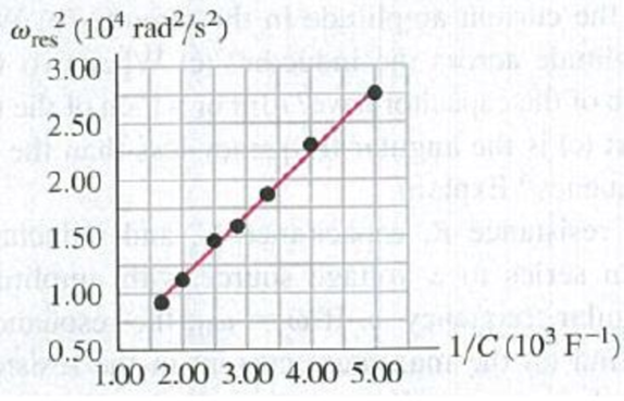
DATA You are analyzing an ac circuit that contains a solenoid and a capacitor in series with an ac source that has voltage amplitude 90.0 V and angular frequency ω. For different capacitors in the circuit, each with known capacitance, you measure the value of the frequency ωres for which the current in the circuit is a maximum. You plot your measured values on a graph of ωres2 versus 1/C (Fig. P31.65). The maximum current for each value of C is the same, you note, and equal to 4.50 A. Calculate the resistance and inductance of the solenoid.
Figure P31.65
Want to see the full answer?
Check out a sample textbook solution
Chapter 31 Solutions
University Physics with Modern Physics (14th Edition)
Additional Science Textbook Solutions
Life in the Universe (4th Edition)
University Physics Volume 1
Physics for Scientists and Engineers: A Strategic Approach, Vol. 1 (Chs 1-21) (4th Edition)
Sears And Zemansky's University Physics With Modern Physics
Lecture- Tutorials for Introductory Astronomy
Essential University Physics (3rd Edition)


- An PLC series circuit with R=600 , L = 30 mH. and c=0.050F is driven by an ac source whose frequency and voltage amplitude are 500 Hz and 50 V, respectively, (a) What is the impedance of the circuit? (b) What is the amplitude of the current in the circuit? (c) What is the phase angle between the emf of the source and the current?arrow_forwardThe emf of an ac source is given by v(t)=V0sint, where V0=100V and =200 . Find an expression that represents the output current of the source if it is connected across (a) a 20-pF capacitor, (b) a 20-mH inductor, and (c) a 50 resistor.arrow_forwardIn the AC circuit shown in Figure P32.3, R = 70.0 and the output voltage of the AC source is Vmax sin t. (a) If VR = 0.250 Vmax for the first time at t = 0.0100 s, what is the angular frequency of the source? (b) What is the next value of t for which VR = 0.250 Vmax? Figure P32.6 Problem 3 and 5.arrow_forward
- When a wire carries an AC current with a known frequency, you can use a Rogowski coil to determine the amplitude Imax of the current without disconnecting the wire to shunt the current through a meter. The Rogowski coil, shown in Figure P23.8, simply clips around the wire. It consists of a toroidal conductor wrapped around a circular return cord. Let n represent the number of turns in the toroid per unit distance along it. Let A represent the cross-sectional area of the toroid. Let I(t) = Imax sin t represent the current to be measured. (a) Show that the amplitude of the emf induced in the Rogowski coil is Emax=0nAImax. (b) Explain why the wire carrying the unknown current need not be at the center of the Rogowski coil and why the coil will not respond to nearby currents that it does not enclose. Figure P23.8arrow_forwardIn a purely inductive AC circuit as shown in Figure P32.6, Vmax = 100 V. (a) The maximum current is 7.50 A at 50.0 Hz. Calculate the inductance L. (b) What If? At what angular frequency is the maximum current 2.50 A? Figure P32.6 Problem 6 and 7.arrow_forwardProblems 71 and 72 paired. Figure P33.71 shows a series RLC circuit with a 25.0- resistor, a 430.0-mH inductor, and a 24.0-F capacitor connected to an AC source with Vmax = 60.0 V operating at 60.0 Hz. What is the maximum voltage across the a. resistor, b. inductor, and c. capacitor in the circuit? FIGURE P33.71 Problems 71 and 72.arrow_forward
- An AC source with Vmax = 150 V and f = 50.0 Hz is connected between points a and d in Figure P32.16. Calculate the maximum voltages between (a) points a and b, (b) points b and c, (c) points c and d, and (d) points b and d. Figure P32.16 Problems 16 and 51.arrow_forwardA 60.0- resistor is connected in series with a 30.0-F capacitor and a generator having a maximum voltage of 1.20 102 V and operating at 60.0 Hz. Find the (a) capacitive reactance of the circuit, (b) impedance of the circuit, and (c) maximum current in the circuit. (d) Does the voltage lead or lag the current? (e) How will putting an inductor in series with the existing capacitor and resistor affect the current? Explain.arrow_forwardA series RLC circuit driven by a source with an amplitude of 120.0 V and a frequency of 50.0 Hz has an inductance of 787 mH, a resistance of 267 , and a capacitance of 45.7 F. a. What are the maximum current and the phase angle between the current and the source emf in this circuit? b. What are the maximum potential difference across the inductor and the phase angle between this potential difference and the current in the circuit? c. What are the maximum potential difference across the resistor and the phase angle between this potential difference and the current in this circuit? d. What are the maximum potential difference across the capacitor and the phase angle between this potential difference and the current in this circuit?arrow_forward
 College PhysicsPhysicsISBN:9781285737027Author:Raymond A. Serway, Chris VuillePublisher:Cengage Learning
 College PhysicsPhysicsISBN:9781305952300Author:Raymond A. Serway, Chris VuillePublisher:Cengage Learning
 Physics for Scientists and Engineers: Foundations...PhysicsISBN:9781133939146Author:Katz, Debora M.Publisher:Cengage Learning
 Physics for Scientists and Engineers, Technology ...PhysicsISBN:9781305116399Author:Raymond A. Serway, John W. JewettPublisher:Cengage Learning
 Principles of Physics: A Calculus-Based TextPhysicsISBN:9781133104261Author:Raymond A. Serway, John W. JewettPublisher:Cengage Learning