Physics for Scientists and Engineers
9th Edition
ISBN: 9781133947271
Author: Raymond A. Serway, John W. Jewett
Publisher: Cengage Learning
expand_more
expand_more
format_list_bulleted
Videos
Textbook Question
Chapter 32, Problem 32.8CQ
After the switch is dosed in the LC circuit shown in Figure CQ32.8, the charge on the capacitor is sometimes zero, but at such instants the current in the circuit is not zero. How is this behavior possible?
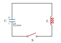
Figure CQ32.8 Conceptual Question 8 and Problems 52, 54, and. 15.
Expert Solution & Answer
Want to see the full answer?
Check out a sample textbook solution
Students have asked these similar questions
One application of an RL circuit is the generation of time-varying high voltage from a low-voltage source. As shown in the figure below, R1
15.0V. What is the current in the inductor a long time after the switch has been in position A? 1.25 A
B
E
L
R₁
w
R₁₂
=
103002, R2
=
12.0, L = 1.82H and ε =
An LC circuit contains a 20 mH inductor and a 50 µF capacitor with an initial charge of 10 mC. The resistance of the circuit is negligible. Let the instant the circuit is closed be t = 0. What is the total energy stored initially? Is it conserved during LC oscillations?
An RLC circuit consists of a 69.3 2 resistor, a 3.66 µF capacitor, and a 73.5 mH inductor. Initially, the voltage across the capacitor is
1.20 V, and no current is flowing in the circuit. What is the magnitude of the charge on the capacitor after 0.0104 s? It is not
acceptable to let w' = w.
i
nC
Chapter 32 Solutions
Physics for Scientists and Engineers
Ch. 32 - A coil with zero resistance has its ends labeled a...Ch. 32 - Prob. 32.2QQCh. 32 - Prob. 32.3QQCh. 32 - Prob. 32.4QQCh. 32 - (i) At an instant of time during the oscillations...Ch. 32 - Prob. 32.1OQCh. 32 - Prob. 32.2OQCh. 32 - Prob. 32.3OQCh. 32 - In Figure OQ32.4, the switch is left in position a...Ch. 32 - Prob. 32.5OQ
Ch. 32 - Prob. 32.6OQCh. 32 - Prob. 32.7OQCh. 32 - Prob. 32.1CQCh. 32 - Prob. 32.2CQCh. 32 - A switch controls the current in a circuit that...Ch. 32 - Prob. 32.4CQCh. 32 - Prob. 32.5CQCh. 32 - Prob. 32.6CQCh. 32 - The open switch in Figure CQ32.7 is thrown closed...Ch. 32 - After the switch is dosed in the LC circuit shown...Ch. 32 - Prob. 32.9CQCh. 32 - Discuss the similarities between the energy stored...Ch. 32 - Prob. 32.1PCh. 32 - Prob. 32.2PCh. 32 - Prob. 32.3PCh. 32 - Prob. 32.4PCh. 32 - An emf of 24.0 mV Ls induced in a 500-turn coil...Ch. 32 - Prob. 32.6PCh. 32 - Prob. 32.7PCh. 32 - Prob. 32.8PCh. 32 - Prob. 32.9PCh. 32 - Prob. 32.10PCh. 32 - Prob. 32.11PCh. 32 - A toroid has a major radius R and a minor radius r...Ch. 32 - Prob. 32.13PCh. 32 - Prob. 32.14PCh. 32 - Prob. 32.15PCh. 32 - Prob. 32.16PCh. 32 - Prob. 32.17PCh. 32 - Prob. 32.18PCh. 32 - Prob. 32.19PCh. 32 - When the switch in Figure P32.18 is closed, the...Ch. 32 - Prob. 32.21PCh. 32 - Show that i = Iiet/ is a solution of the...Ch. 32 - Prob. 32.23PCh. 32 - Consider the circuit in Figure P32.18, taking =...Ch. 32 - Prob. 32.25PCh. 32 - The switch in Figure P31.15 is open for t 0 and...Ch. 32 - Prob. 32.27PCh. 32 - Prob. 32.28PCh. 32 - Prob. 32.29PCh. 32 - Two ideal inductors, L1 and L2, have zero internal...Ch. 32 - Prob. 32.31PCh. 32 - Prob. 32.32PCh. 32 - Prob. 32.33PCh. 32 - Prob. 32.34PCh. 32 - Prob. 32.35PCh. 32 - Complete the calculation in Example 31.3 by...Ch. 32 - Prob. 32.37PCh. 32 - A flat coil of wire has an inductance of 40.0 mH...Ch. 32 - Prob. 32.39PCh. 32 - Prob. 32.40PCh. 32 - Prob. 32.41PCh. 32 - Prob. 32.42PCh. 32 - Prob. 32.43PCh. 32 - Prob. 32.44PCh. 32 - Prob. 32.45PCh. 32 - Prob. 32.46PCh. 32 - In the circuit of Figure P31.29, the battery emf...Ch. 32 - A 1.05-H inductor is connected in series with a...Ch. 32 - A 1.00-F capacitor is charged by a 40.0-V power...Ch. 32 - Calculate the inductance of an LC circuit that...Ch. 32 - An LC circuit consists of a 20.0-mH inductor and a...Ch. 32 - Prob. 32.52PCh. 32 - Prob. 32.53PCh. 32 - Prob. 32.54PCh. 32 - An LC circuit like the one in Figure CQ32.8...Ch. 32 - Show that Equation 32.28 in the text Ls Kirchhoffs...Ch. 32 - In Figure 31.15, let R = 7.60 , L = 2.20 mH, and C...Ch. 32 - Consider an LC circuit in which L = 500 mH and C=...Ch. 32 - Electrical oscillations are initiated in a series...Ch. 32 - Review. Consider a capacitor with vacuum between...Ch. 32 - Prob. 32.61APCh. 32 - An inductor having inductance I. and a capacitor...Ch. 32 - A capacitor in a series LC circuit has an initial...Ch. 32 - Prob. 32.64APCh. 32 - When the current in the portion of the circuit...Ch. 32 - At the moment t = 0, a 24.0-V battery is connected...Ch. 32 - Prob. 32.67APCh. 32 - Prob. 32.68APCh. 32 - Prob. 32.69APCh. 32 - At t = 0, the open switch in Figure P31.46 is...Ch. 32 - Prob. 32.71APCh. 32 - Prob. 32.72APCh. 32 - Review. A novel method of storing energy has been...Ch. 32 - Prob. 32.74APCh. 32 - Review. The use of superconductors has been...Ch. 32 - Review. A fundamental property of a type 1...Ch. 32 - Prob. 32.77APCh. 32 - In earlier times when many households received...Ch. 32 - Assume the magnitude of the magnetic field outside...Ch. 32 - Prob. 32.80CPCh. 32 - To prevent damage from arcing in an electric...Ch. 32 - One application of an RL circuit is the generation...Ch. 32 - Prob. 32.83CP
Knowledge Booster


Learn more about
Need a deep-dive on the concept behind this application? Look no further. Learn more about this topic, physics and related others by exploring similar questions and additional content below.Similar questions
- An inductor and a resistor are connected in series across an AC source as in Figure OQ33.1. Immediately after the switch is closed, which of the following statements is true? (a) The current in the circuit is V/R. (b) The voltage across the inductor is zero, (c) The current in the circuit is zero, (d) The voltage across the resistor is V (e) The voltage across the inductor is half its maximum value.arrow_forwardIn the transformer shown in Figure P33.51, the load resistance RL is 50.0 . The turns ratio N1/N2 is 2.50, anti the rms source voltage is Vs = 80.0 V. If a voltmeter across the load resistance measures an rms voltage of 25.0 V, what is the source resistance Rs?arrow_forwardAn inductor and a resistor are connected in series across an AC generator, as shown in Figure CQ21.16. Immediately after the switch is closed, which of the following statements is true? (a) The current is V/R. (b) The voltage across the inductor is zero. (c) The current in the circuit is zero. (d) The voltage across the resistor is V. (e) The voltage across the inductor is half its maximum value. Figure CQ21.16arrow_forward
- An inductor and a resistor are connected in series across an AC generator, as shown in Figure CQ21.16. Immediately after the switch is closed, which of the following statements is true? (a) The current is V/R. (b) The voltage across the inductor is zero. (c) The current in the circuit is zero. (d) The voltage across the resistor is V. (e) The voltage across the inductor is half its maximum value. Figure CQ21.16arrow_forwardIn an oscillating RLC circuit, R = 7.0 L. = 10 mH. And C = 3.0 F. Initially, the capacitor has a charge of 8.0 C and the current is zero. Calculate the charge on the capacitor (a) five cycles later and (b) 50 cycles later.arrow_forwardIn the LC circuit in Figure 33.11, the inductance is L = 19.8 mH and the capacitance is C = 19.6 mF. At some moment, UB = UE= 17.5 mJ. a. What is the maximum charge stored by the capacitor? b. What is the maximum current in the circuit? c. At t = 0, the capacitor is fully charged. Write an expression for the charge stored by the capacitor as a function of lime. d. Write an expression for the current as a function of time.arrow_forward
- In a purely inductive AC circuit as shown in Figure P32.6, Vmax = 100 V. (a) The maximum current is 7.50 A at 50.0 Hz. Calculate the inductance L. (b) What If? At what angular frequency is the maximum current 2.50 A? Figure P32.6 Problem 6 and 7.arrow_forwardProblems 71 and 72 paired. Figure P33.71 shows a series RLC circuit with a 25.0- resistor, a 430.0-mH inductor, and a 24.0-F capacitor connected to an AC source with Vmax = 60.0 V operating at 60.0 Hz. What is the maximum voltage across the a. resistor, b. inductor, and c. capacitor in the circuit? FIGURE P33.71 Problems 71 and 72.arrow_forwardWhen a wire carries an AC current with a known frequency, you can use a Rogowski coil to determine the amplitude Imax of the current without disconnecting the wire to shunt the current through a meter. The Rogowski coil, shown in Figure P23.8, simply clips around the wire. It consists of a toroidal conductor wrapped around a circular return cord. Let n represent the number of turns in the toroid per unit distance along it. Let A represent the cross-sectional area of the toroid. Let I(t) = Imax sin t represent the current to be measured. (a) Show that the amplitude of the emf induced in the Rogowski coil is Emax=0nAImax. (b) Explain why the wire carrying the unknown current need not be at the center of the Rogowski coil and why the coil will not respond to nearby currents that it does not enclose. Figure P23.8arrow_forward
- × Incorrect. In an oscillating LC circuit, L = 1.04 mH and C = 4.71 μF. The maximum charge on the capacitor is 2.52 μC. Find the maximum current. Number i 1.10 Units No unitsarrow_forwardAn RL circuit has an emf source of 28 v, a 62 resistor, a 38 H inductor, and a switch. At what rate, as a function of t, does the emf across the inductor change after the switch is closed?arrow_forwardA battery of emf E is connected in series with a resistor, an inductor L, and a switch S. A capacitor C is connected in parallel to the inductor. When the switch is left in the closed position for a long time, the potential difference across the capacitor is zero. The switch is opened and the maximum potential difference across the capacitor is measured to be 140 V. Determine the capacitance of the capacitor if E = 60 V, R = 125 N, and L = 54.0 mH. ww Rarrow_forward
arrow_back_ios
SEE MORE QUESTIONS
arrow_forward_ios
Recommended textbooks for you
 Physics for Scientists and Engineers, Technology ...PhysicsISBN:9781305116399Author:Raymond A. Serway, John W. JewettPublisher:Cengage Learning
 Principles of Physics: A Calculus-Based TextPhysicsISBN:9781133104261Author:Raymond A. Serway, John W. JewettPublisher:Cengage Learning
 Physics for Scientists and EngineersPhysicsISBN:9781337553278Author:Raymond A. Serway, John W. JewettPublisher:Cengage Learning
 Physics for Scientists and Engineers with Modern ...PhysicsISBN:9781337553292Author:Raymond A. Serway, John W. JewettPublisher:Cengage Learning
 Physics for Scientists and Engineers: Foundations...PhysicsISBN:9781133939146Author:Katz, Debora M.Publisher:Cengage Learning
Physics for Scientists and Engineers, Technology ...
Physics
ISBN:9781305116399
Author:Raymond A. Serway, John W. Jewett
Publisher:Cengage Learning
Principles of Physics: A Calculus-Based Text
Physics
ISBN:9781133104261
Author:Raymond A. Serway, John W. Jewett
Publisher:Cengage Learning
Physics for Scientists and Engineers
Physics
ISBN:9781337553278
Author:Raymond A. Serway, John W. Jewett
Publisher:Cengage Learning
Physics for Scientists and Engineers with Modern ...
Physics
ISBN:9781337553292
Author:Raymond A. Serway, John W. Jewett
Publisher:Cengage Learning
Physics for Scientists and Engineers: Foundations...
Physics
ISBN:9781133939146
Author:Katz, Debora M.
Publisher:Cengage Learning
Introduction To Alternating Current; Author: Tutorials Point (India) Ltd;https://www.youtube.com/watch?v=0m142qAZZpE;License: Standard YouTube License, CC-BY