Videos
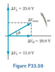
Review. The voltage phasor diagram for a certain series RLC circuit is shown in Figure P33.59. The resistance of the circuit is 75.0 Ω, and the frequency is 60.0 Hz. Find (a) the maximum voltage ΔVmax, (b) the phase angle ϕ, (c) the maximum current, (d) the impedance, (e) the capacitance and (f) the inductance of the circuit, and (g) the average power delivered to the circuit.
(a)
The maximum voltage.
Answer to Problem 33.59AP
The maximum voltage is
Explanation of Solution
Given info: The resistance of the circuit is
The expression for maximum value of the voltage is,
Here,
Substitute
Conclusion:
Therefore, the maximum voltage is
(b)
The phase angle.
Answer to Problem 33.59AP
The phase angle is
Explanation of Solution
Given info: The resistance of the circuit is
The expression for the phase angle is,
Substitute
Conclusion:
Therefore, the phase angle is
(c)
The maximum current.
Answer to Problem 33.59AP
The maximum current is
Explanation of Solution
Given info: The resistance of the circuit is
The expression for maximum current is,
Here,
Substitute
Conclusion:
Therefore, the maximum current is
(d)
The impedance.
Answer to Problem 33.59AP
The impedance is
Explanation of Solution
Given info: The resistance of the circuit is
The expression for the impedance is,
Substitute
Conclusion:
Therefore, the impedance is
(e)
The capacitance.
Answer to Problem 33.59AP
The capacitance is
Explanation of Solution
Given info: The resistance of the circuit is
The circuit is series
The expression capacitive reactance is,
Substitute
The expression capacitive reactance in terms of the capacitance is,
Here,
Rearrange the above equation for the value of capacitance.
Substitute
Conclusion:
Therefore, the capacitance is
(f)
The inductance of the circuit.
Answer to Problem 33.59AP
The inductance of the circuit
Explanation of Solution
Given info: The resistance of the circuit is
The circuit is series
The expression inductive reactance is,
Substitute
Thus the value of inductive reactance is
The expression inductive reactance in terms of the inductance is,
Here,
Rearrange the above equation for the value of inductance.
Substitute
Conclusion:
Therefore, the inductance is
(g)
The average power delivered to circuit.
Answer to Problem 33.59AP
The average power delivered to circuit is
Explanation of Solution
Given info: The resistance of the circuit is
The expression for R.M.S value of the current is,
The expression for the average power delivered is,
Substitute
Substitute
Conclusion:
Therefore, the average power delivered to circuit is
Want to see more full solutions like this?
Chapter 33 Solutions
PHYSICS:F/SCI.+.,V.2-STUD.S.M.+STD.GDE.


- An inductor and a resistor are connected in series across an AC source as in Figure OQ33.1. Immediately after the switch is closed, which of the following statements is true? (a) The current in the circuit is V/R. (b) The voltage across the inductor is zero, (c) The current in the circuit is zero, (d) The voltage across the resistor is V (e) The voltage across the inductor is half its maximum value.arrow_forwardProblems 71 and 72 paired. Figure P33.71 shows a series RLC circuit with a 25.0- resistor, a 430.0-mH inductor, and a 24.0-F capacitor connected to an AC source with Vmax = 60.0 V operating at 60.0 Hz. What is the maximum voltage across the a. resistor, b. inductor, and c. capacitor in the circuit? FIGURE P33.71 Problems 71 and 72.arrow_forwardIn the LC circuit in Figure 33.11, the inductance is L = 19.8 mH and the capacitance is C = 19.6 mF. At some moment, UB = UE= 17.5 mJ. a. What is the maximum charge stored by the capacitor? b. What is the maximum current in the circuit? c. At t = 0, the capacitor is fully charged. Write an expression for the charge stored by the capacitor as a function of lime. d. Write an expression for the current as a function of time.arrow_forward
- In a purely inductive AC circuit as shown in Figure P32.6, Vmax = 100 V. (a) The maximum current is 7.50 A at 50.0 Hz. Calculate the inductance L. (b) What If? At what angular frequency is the maximum current 2.50 A? Figure P32.6 Problem 6 and 7.arrow_forwardA series RLC circuit driven by a source with an amplitude of 120.0 V and a frequency of 50.0 Hz has an inductance of 787 mH, a resistance of 267 , and a capacitance of 45.7 F. a. What are the maximum current and the phase angle between the current and the source emf in this circuit? b. What are the maximum potential difference across the inductor and the phase angle between this potential difference and the current in the circuit? c. What are the maximum potential difference across the resistor and the phase angle between this potential difference and the current in this circuit? d. What are the maximum potential difference across the capacitor and the phase angle between this potential difference and the current in this circuit?arrow_forwardConsider the Filter circuit shown in Figure P33.56. (a) Show that the ratio of the amplitude of the output voltage to that of the input voltage is to that of input voltage is VoutVin=1/CR2+(1C)2 (b) What value does this ratio approach as the frequency decreases toward zero? (c) What value does this ratio approach as the frequency increases without limit? (d) At what frequency is the ratio equal to one-half?arrow_forward
- An RLC series circuit with R = 600 Ω, L = 30 mH,and C = 0.050µF is driven by an ac source whosefrequency and voltage amplitude are 500 Hz and 50 V,respectively. (a) What is the impedance of the circuit? (b)What is the amplitude of the current in the circuit? (c) Whatis the phase angle between the emf of the source and the current?arrow_forwardA resistor ( R = 9.00 × 10² Ω), a capacitor (C = 0.250 µF), and an inductor (L = 2.50 H) are connected in series across a 2.40 × 10²-Hz AC source for which ΔV max = 1.40 × 10² V. Calculate (a) the impedance of the circuit, (b) the maximum current delivered by the source, and (c) the phase angle between the current and voltage. (d) Is the current leading or lagging the voltage?arrow_forwardA sinusoidal voltage where Vmax = 100.0 V and a frequency of 60 Hz is applied to a series RLC circuit with L = 186 mH, C = 88.4 µF, and R = 30.0 Ω. (a) What is the capacitive reactance? (b) What is the inductive reactance? (c) What is the impedance of the circuit? (d) What is the rms voltage? (e) At what frequency would this combination of inductor, L, and capacitor, C, be at resonance?arrow_forward
- An RLC series circuit is constructed with R = 150.0 Ω, C = 7.50 µF, and L = 0.54 H. The circuit is connected to an AC generator with a frequency of 60.0 Hz that delivers a maximum current of 1.70 A to the circuit. (a) What is the impedance of this circuit? Ω(b) What are the maximum potential differences across each of the three circuit elements (R, L, and C)? VR, max = V VL, max = V VC, max = V (c) What is the phase angle between the source emf and the current? radarrow_forwardIn an oscillating LC circuit, L = 25.0 mH and C = 7.80 mF. At time t 0 the current is 9.20 mA, the charge on the capacitor is 3.80 mC, and the capacitor is charging.What are (a) the total energy in the circuit, (b) the maximum charge on the capacitor, and (c) the maximum current? (d) If the charge on the capacitor is given by q = Q cos(vt + f), what is the phase angle f? (e) Suppose the data are the same, except that the capacitor is discharging at t = 0.What then is f?arrow_forwardIn an oscillating LC circuit in which C = 4.5 μF, the maximum potential difference across the capacitor during the oscillations is 1.5 V and the maximum current through the inductor is 52.8 mA. What are (a) the inductance L and (b) the frequency of the oscillations? (c) How much time is required for the charge on the capacitor to rise from zero to its maximum value?arrow_forward
 Physics for Scientists and Engineers: Foundations...PhysicsISBN:9781133939146Author:Katz, Debora M.Publisher:Cengage Learning
 Physics for Scientists and EngineersPhysicsISBN:9781337553278Author:Raymond A. Serway, John W. JewettPublisher:Cengage Learning
 Physics for Scientists and Engineers with Modern ...PhysicsISBN:9781337553292Author:Raymond A. Serway, John W. JewettPublisher:Cengage Learning
 Physics for Scientists and Engineers, Technology ...PhysicsISBN:9781305116399Author:Raymond A. Serway, John W. JewettPublisher:Cengage Learning