
Mechanics of Materials (10th Edition)
10th Edition
ISBN: 9780134319650
Author: Russell C. Hibbeler
Publisher: PEARSON
expand_more
expand_more
format_list_bulleted
Concept explainers
Videos
Textbook Question
Chapter 3.4, Problem 3.18P
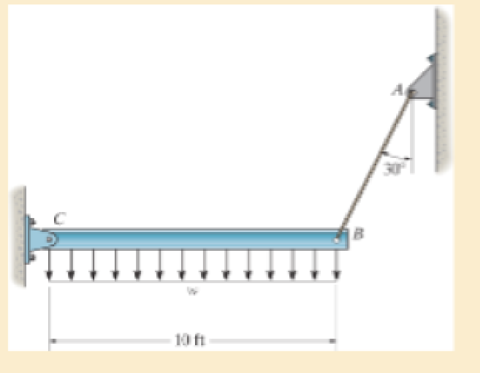
The rigid beam is supported by a pin at C and an A992 steel guy wire AB of length 6 ft. If the wire has a diameter of 0.2 in., determine the distributed load w if the end B is displaced 0.12 in. downward. The wire remains elastic.
Expert Solution & Answer
Want to see the full answer?
Check out a sample textbook solution
Students have asked these similar questions
The rigid beam is supported by a pin at C and an A992 steel guy wire AB of length 6 ft. If the wire has a diameter of 0.2 in., determine how much it stretches when a distributed load of w = 200 lb>ft acts on the beam. The wire remains elastic.
The rigid beam is supported by a pin at C and an A-36 steel guy wire AB. If the wire has a diameter of 0.2 in., determine how much it stretches when a distributed load of w = 100 lb>ft acts on the beam. The material remains elastic.
A steel column has a length of 9 m and is pinned at its top and bottom. If the cross-sectional area has the dimensions shown, determine the critical load. Est = 200 GPa, sY = 250 MPa.
Chapter 3 Solutions
Mechanics of Materials (10th Edition)
Ch. 3.4 - Define a homogeneous material.Ch. 3.4 - Indicate the points on the stress-strain diagram...Ch. 3.4 - Define the modulus of elasticity E.Ch. 3.4 - At room temperature, mild steel is a ductile...Ch. 3.4 - Engineering stress and strain are calculated using...Ch. 3.4 - As the temperature increases the modulus of...Ch. 3.4 - A 100-mm-long rod has a diameter of 15 mm. If an...Ch. 3.4 - A bar has a length of 8 in. and cross-sectional...Ch. 3.4 - A 10-mm-diameter rod has a modulus of elasticity...Ch. 3.4 - The material for the 50-mm-long specimen has the...
Ch. 3.4 - The material for the 50-mm-long specimen has the...Ch. 3.4 - If the elongation of wire BC is 0.2 mm after the...Ch. 3.4 - A tension test was performed on a steel specimen...Ch. 3.4 - Data taken from a stress-strain test for a ceramic...Ch. 3.4 - Data taken from a stress-strain test for a ceramic...Ch. 3.4 - The stress-strain diagram for a steel alloy having...Ch. 3.4 - The stress-strain diagram for a steel alloy having...Ch. 3.4 - The stress-strain diagram for a steel alloy having...Ch. 3.4 - The rigid beam is supported by a pin at C and an...Ch. 3.4 - The rigid beam is supported by a pin at C and an...Ch. 3.4 - Acetal plastic has a stress-strain diagram as...Ch. 3.4 - The stress-strain diagram for an aluminum alloy...Ch. 3.4 - The stress-strain diagram for an aluminum alloy...Ch. 3.4 - The stress-strain diagram for an aluminum alloy...Ch. 3.4 - A bar having a length of 5 in. and cross-sectional...Ch. 3.4 - The rigid pipe is supported by a pin at A and an...Ch. 3.4 - The rigid pipe is supported by a pin at A and an...Ch. 3.4 - Direct tension indicators are sometimes used...Ch. 3.4 - The rigid beam is supported by a pin at C and an...Ch. 3.4 - The rigid beam is supported by a pin at C and an...Ch. 3.4 - The stress-strain diagram for a bone is shown, and...Ch. 3.4 - The stress-strain diagram for a bone is shown and...Ch. 3.4 - The two bars are made of a material that has the...Ch. 3.4 - The two bars are made of a material that has the...Ch. 3.4 - The pole is supported by a pin at C and an A-36...Ch. 3.4 - The bar DA is rigid and is originally held in the...Ch. 3.7 - A 100-mm-long rod has a diameter of 15 mm. If an...Ch. 3.7 - A solid circular rod that is 600 mm long and 20 mm...Ch. 3.7 - A 20-mm-wide block is firmly bonded to rigid...Ch. 3.7 - A 20-mm-wide block is bonded to rigid plates at...Ch. 3.7 - The acrylic plastic rod is 200 mm long and 15 mm...Ch. 3.7 - The plug has a diameter of 30 mm and fits within a...Ch. 3.7 - The elastic portion of the stress-strain diagram...Ch. 3.7 - The elastic portion of the stress-strain diagram...Ch. 3.7 - The brake pads for a bicycle tire are made of...Ch. 3.7 - The lap joint is connected together using a 1.25...Ch. 3.7 - The lap joint is connected together using a 1.25...Ch. 3.7 - The rubber block is subjected to an elongation of...Ch. 3.7 - The shear stress-strain diagram for an alloy is...Ch. 3.7 - A shear spring is made from two blocks of rubber,...Ch. 3 - The elastic portion of the tension stress-strain...Ch. 3 - The elastic portion of the tension stress-strain...Ch. 3 - The rigid beam rests in the horizontal position on...Ch. 3 - The wires each have a diameter of 12 in., length...Ch. 3 - The wires each have a diameter of 12 in., length...Ch. 3 - diameter steel bolts. If the clamping force in...Ch. 3 - The stress-strain diagram for polyethylene, which...Ch. 3 - The pipe with two rigid caps attached to its ends...Ch. 3 - The 8-mm-diameter bolt is made of an aluminum...Ch. 3 - An acetal polymer block is fixed to the rigid...
Knowledge Booster


Learn more about
Need a deep-dive on the concept behind this application? Look no further. Learn more about this topic, mechanical-engineering and related others by exploring similar questions and additional content below.Similar questions
- The rigid beam is supported by a pin at C and an A-36 steel guy wire AB. If the wire has a diameter of 0.2 in., determine the distributed load w if the end B is displaced 0.75 in. downward.arrow_forwardThe rigid beam rests in the horizontal position on two 2014-T6 aluminum cylinders having the unloaded lengths shown. If each cylinder has a diameter of 30 mm, determine the placement x of the applied 80-kN load so that the beam remains horizontal. What is the new diameter of cylinder A after the load is applied? nal = 0.35.arrow_forwardA 20-ft-long column is made of aluminum alloy 2014-T6. If it is pinned at its top and bottom, and a compressive load P is applied at point A, determine the maximum allowable magnitude of P using the equations of Sec. 13.6 and Eq. 13–30.arrow_forward
- A steel column has a length of 9 m and is fixed at both ends. If the cross-sectional area has the dimensions shown, determine the critical load. Est = 200 GPa, sY = 250 MPa.arrow_forwardThe strut is supported by a pin at C and an A-36 steel (Young’s Modulus is 200 GPa) guy wire AB. If the wire has a diameter of 5 mm, determine how much it stretches when the distributed load acts on the strut. W0=11Kn/marrow_forwardThe 304 stainless steel post A is surrounded by a red brass C83400 tube B. Both rest on the rigid surface. If a force of 25 kN is applied to the rigid cap, determine the required diameter d of the steel post so that the load is shared equally between the post and tube. The elastic modulus for brass is 101 GPa and the elastic modulus for steel is 193 GPaarrow_forward
- The 10-ft-long bar is made of aluminum alloy 2014-T6. If it is fixed at its bottom and pinned at the top, determine the maximum allowable eccentric load P that can be applied using the formulas in Sec. 13.6 and Eq. 13–30.arrow_forwardThe truss is made from A992 steel bars, each of which has a circular cross section. If the applied load P = 10 kip, determine the diameter of member AB to the nearest 1/8 in. that will prevent this member from buckling. The members are pin connected at their ends.arrow_forwardThe A992 steel bars are pin connected at C and D. If they each have the same rectangular cross-section, with a height of 200 mm and a width of 100 mm, determine the vertical displacement at B. Neglect the axial load in the bars.arrow_forward
- A steel column is of length 8m and diameter 600 mm with both ends hinged.Determine the crippling load by Euler’s formula. Take 5 E = 2.1x10 N/mm2arrow_forwardDetermine the maximum allowable eccentric load P that can be applied to the wood column. The column is fixed at its base and free at its top. Use the NFPA equations of Sec. 13.6 and Eq. 13–30.arrow_forwardA steel pipe is fixed supported at its ends. If it is 5 m long and has an outer diameter of 50 mm and a thickness of 10 mm, determine the maximum axial load P that it can carry without buckling. Est = 200 GPa, sY = 250 MPa.arrow_forward
arrow_back_ios
SEE MORE QUESTIONS
arrow_forward_ios
Recommended textbooks for you
 Mechanics of Materials (MindTap Course List)Mechanical EngineeringISBN:9781337093347Author:Barry J. Goodno, James M. GerePublisher:Cengage Learning
Mechanics of Materials (MindTap Course List)
Mechanical Engineering
ISBN:9781337093347
Author:Barry J. Goodno, James M. Gere
Publisher:Cengage Learning
EVERYTHING on Axial Loading Normal Stress in 10 MINUTES - Mechanics of Materials; Author: Less Boring Lectures;https://www.youtube.com/watch?v=jQ-fNqZWrNg;License: Standard YouTube License, CC-BY