
Mechanics of Materials (10th Edition)
10th Edition
ISBN: 9780134319650
Author: Russell C. Hibbeler
Publisher: PEARSON
expand_more
expand_more
format_list_bulleted
Videos
Textbook Question
Chapter 3, Problem 3.7RP
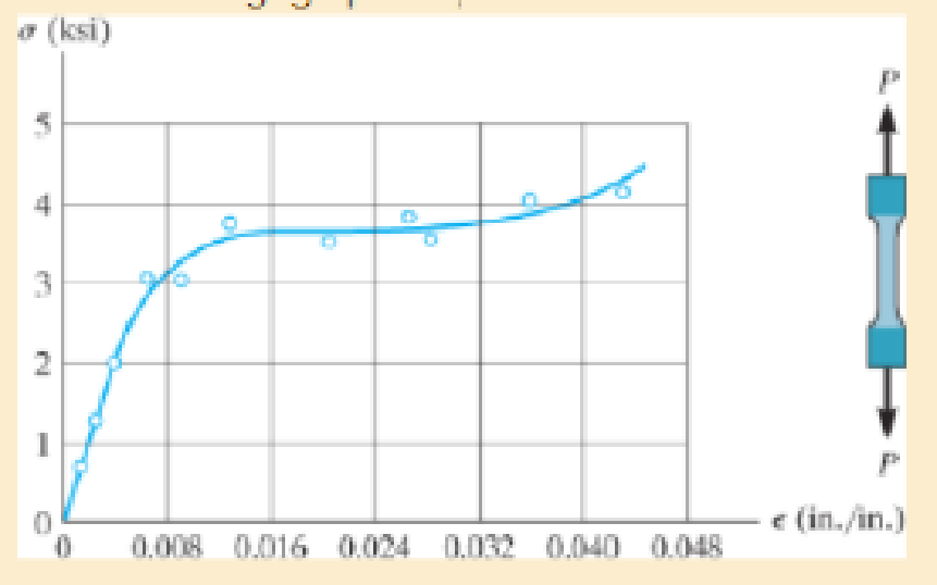
The stress-strain diagram for polyethylene, which is used to sheath coaxial cables, is determined from testing a specimen that has a gage length of 10 in. If a load P on the specimen develops a strain of ε = 0.024 in./in., determine the approximate length of the specimen, measured between the gage points, when the load is removed. Assume the specimen recovers elastically.
Expert Solution & Answer
Want to see the full answer?
Check out a sample textbook solution
Students have asked these similar questions
The stress–strain diagram for polyethylene, which is used to sheath coaxial cables, is determined from testing a specimen that has a gage length of 10 in. If a load P on the specimen develops a strain of P = 0.024 in.>in., determinethe approximate length of the specimen, measured between the gage points, when the load is removed. Assume the specimen recovers elastically
a) A thin strip of rubber-like material has an unstretched length of 345 mm.i. If it is stretched around a pipe having an outer diameter of 112 mm, determine the average normal strain in the strip, assuming linear elastic behaviour. (3 marks)ii. A steel wire of diameter dwire = 1.5 mm also has an initial length of 345 mm. The Young’s Modulus of the steel material is 190 GPa and its yield strength is 275 MPa. What is the maximum pipe diameter that the wire can be stretched around without yielding and what is the magnitude of the tensile force in the wire for this elongation? Give your answers to two decimal places
7) The strain of a component, which has a tensile modulus of 4 X 10⁵ MPa, and subjected to a stress of 6000KPa, is
a.
0.000015
b.
0.00015
c.
0.00003
d.
0.003
Chapter 3 Solutions
Mechanics of Materials (10th Edition)
Ch. 3.4 - Define a homogeneous material.Ch. 3.4 - Indicate the points on the stress-strain diagram...Ch. 3.4 - Define the modulus of elasticity E.Ch. 3.4 - At room temperature, mild steel is a ductile...Ch. 3.4 - Engineering stress and strain are calculated using...Ch. 3.4 - As the temperature increases the modulus of...Ch. 3.4 - A 100-mm-long rod has a diameter of 15 mm. If an...Ch. 3.4 - A bar has a length of 8 in. and cross-sectional...Ch. 3.4 - A 10-mm-diameter rod has a modulus of elasticity...Ch. 3.4 - The material for the 50-mm-long specimen has the...
Ch. 3.4 - The material for the 50-mm-long specimen has the...Ch. 3.4 - If the elongation of wire BC is 0.2 mm after the...Ch. 3.4 - A tension test was performed on a steel specimen...Ch. 3.4 - Data taken from a stress-strain test for a ceramic...Ch. 3.4 - Data taken from a stress-strain test for a ceramic...Ch. 3.4 - The stress-strain diagram for a steel alloy having...Ch. 3.4 - The stress-strain diagram for a steel alloy having...Ch. 3.4 - The stress-strain diagram for a steel alloy having...Ch. 3.4 - The rigid beam is supported by a pin at C and an...Ch. 3.4 - The rigid beam is supported by a pin at C and an...Ch. 3.4 - Acetal plastic has a stress-strain diagram as...Ch. 3.4 - The stress-strain diagram for an aluminum alloy...Ch. 3.4 - The stress-strain diagram for an aluminum alloy...Ch. 3.4 - The stress-strain diagram for an aluminum alloy...Ch. 3.4 - A bar having a length of 5 in. and cross-sectional...Ch. 3.4 - The rigid pipe is supported by a pin at A and an...Ch. 3.4 - The rigid pipe is supported by a pin at A and an...Ch. 3.4 - Direct tension indicators are sometimes used...Ch. 3.4 - The rigid beam is supported by a pin at C and an...Ch. 3.4 - The rigid beam is supported by a pin at C and an...Ch. 3.4 - The stress-strain diagram for a bone is shown, and...Ch. 3.4 - The stress-strain diagram for a bone is shown and...Ch. 3.4 - The two bars are made of a material that has the...Ch. 3.4 - The two bars are made of a material that has the...Ch. 3.4 - The pole is supported by a pin at C and an A-36...Ch. 3.4 - The bar DA is rigid and is originally held in the...Ch. 3.7 - A 100-mm-long rod has a diameter of 15 mm. If an...Ch. 3.7 - A solid circular rod that is 600 mm long and 20 mm...Ch. 3.7 - A 20-mm-wide block is firmly bonded to rigid...Ch. 3.7 - A 20-mm-wide block is bonded to rigid plates at...Ch. 3.7 - The acrylic plastic rod is 200 mm long and 15 mm...Ch. 3.7 - The plug has a diameter of 30 mm and fits within a...Ch. 3.7 - The elastic portion of the stress-strain diagram...Ch. 3.7 - The elastic portion of the stress-strain diagram...Ch. 3.7 - The brake pads for a bicycle tire are made of...Ch. 3.7 - The lap joint is connected together using a 1.25...Ch. 3.7 - The lap joint is connected together using a 1.25...Ch. 3.7 - The rubber block is subjected to an elongation of...Ch. 3.7 - The shear stress-strain diagram for an alloy is...Ch. 3.7 - A shear spring is made from two blocks of rubber,...Ch. 3 - The elastic portion of the tension stress-strain...Ch. 3 - The elastic portion of the tension stress-strain...Ch. 3 - The rigid beam rests in the horizontal position on...Ch. 3 - The wires each have a diameter of 12 in., length...Ch. 3 - The wires each have a diameter of 12 in., length...Ch. 3 - diameter steel bolts. If the clamping force in...Ch. 3 - The stress-strain diagram for polyethylene, which...Ch. 3 - The pipe with two rigid caps attached to its ends...Ch. 3 - The 8-mm-diameter bolt is made of an aluminum...Ch. 3 - An acetal polymer block is fixed to the rigid...
Knowledge Booster


Learn more about
Need a deep-dive on the concept behind this application? Look no further. Learn more about this topic, mechanical-engineering and related others by exploring similar questions and additional content below.Similar questions
- A rigid steel bar is supported by three rods, as shown. There is no strain in the rods before the load P is applied. After load P is applied, the normal strain in rod (2) is 1020 μin./in. Assume initial rod lengths of L1 = 148 in. and L2 = 78 in. Determine(a) the normal strain in rods (1).(b) the normal strain in rods (1) if there is a 0.043 in. gap in the connections between the rigid bar and rods (1) at joints A and C before the load is applied.(c) the normal strain in rods (1) if there is a 0.043 in. gap in the connection between the rigid bar and rod (2) at joint B before the load is applied.arrow_forwardThe strain at point A on the pressure-vessel wall has components Px = 480(10-6), Py = 720(10-6), gxy =650(10-6). Determine (a) the principal strains at A, in the x9y plane, (b) the maximum shear strain in the x9y plane, and (c) the absolute maximum shear strain.arrow_forwardThe rigid beam is supported by a pin at A and wires BD and CE. If the load P on the beam causes the end C to be displaced 15 mm downward, determineA. the normal strain developed in wire CEB. the normal strain developed in wires BD. Show free body diagram and complete solution (no shortcut) SHOW PRESSURE DIAGRAM. THANK YOUarrow_forward
- The polysulfone block is glued at its top and bottom to the rigid plates. If a tangential force, applied to the top plate, causes the material to deform so that its sides are described by the equation y = 3.56 x1>4, determine the shear strain at the corners A and B.arrow_forwardThe head H is connected to the cylinder of a compressor using six 316-in. diameter steel bolts. If the clamping force in each bolt is 800 lb, determine the normal strain in the bolts. If sY = 40 ksi and Est = 2911032 ksi, what is the strain in each bolt when the nut is unscrewed so that the clamping force is released?arrow_forwardThe pin-connected rigid rods AB and BC are inclined at u = 30° when they are unloaded. When the force P is applied u becomes 30.2°. Determine the average normal strain in wire AC.arrow_forward
- The A-36 steel bar consists of two segments, one of a circular cross-section of radius r, and one of square cross-section. If the bar is subjected to the axial loading of P, determine the dimensions of the square segment so that the strain energy within the square segment is the same as in the circular segment.arrow_forwardThe state of strain at the point on the spanner wrench has components of Px = 260(10-6), P y = 320(10-6), and gxy = 180(10-6). Use the strain transformation equations to determine (a) the in-plane principal strains and (b) the maximum in-plane shear strain and average normal strain. In each case specify the orientation of the element and show how the strains deform the element within the x–y plane.arrow_forwardDetermine the strain if a rod is experiencing a stress of 70,000kPa with a modulus of elasticity of 175 GPa.a. 300 x 10−6b. 400 x 10−6c. 500 x 10−6d.. 600 x 10−6arrow_forward
- 5 decimal places Determine the total strain (mm/mm) of a 2.64-m bar with a diameter of 21 mm subjected to a tensile force of 71 kN at a temperature increase of 49 C°. Consider the α=27.3 µm/mC° and E = 122 GPa.arrow_forwardA single strain gage, placed in the vertical plane on the outer surface and at an angle 60° to the axis of the pipe, gives a reading at point A of PA = -250(10-6). Determine the principal strains in the pipe at this point. The pipe has an outer diameter of 1 in. and an inner diameter of 0.6 in. and is made of C86100 bronze.arrow_forwardDetermine the shear strain gxy at corners A and B if the plastic distorts as shown by the dashed lines.arrow_forward
arrow_back_ios
SEE MORE QUESTIONS
arrow_forward_ios
Recommended textbooks for you
 Mechanics of Materials (MindTap Course List)Mechanical EngineeringISBN:9781337093347Author:Barry J. Goodno, James M. GerePublisher:Cengage Learning
Mechanics of Materials (MindTap Course List)
Mechanical Engineering
ISBN:9781337093347
Author:Barry J. Goodno, James M. Gere
Publisher:Cengage Learning
An Introduction to Stress and Strain; Author: The Efficient Engineer;https://www.youtube.com/watch?v=aQf6Q8t1FQE;License: Standard YouTube License, CC-BY