
Mechanics of Materials (10th Edition)
10th Edition
ISBN: 9780134319650
Author: Russell C. Hibbeler
Publisher: PEARSON
expand_more
expand_more
format_list_bulleted
Videos
Textbook Question
Chapter 3, Problem 3.6RP
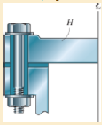
diameter steel bolts. If the clamping force in each bolt is 800 lb, determine the normal strain in the bolts. If σY = 40 ksi and Est = 29 (103) ksi, what is the strain in each bolt when the nut is unscrewed so that the clamping force is released?
Expert Solution & Answer
Want to see the full answer?
Check out a sample textbook solution
Students have asked these similar questions
If the load P on the beam causes the end C to be displaced 10 mm downward, determine the normal strain in wires CE and BD.
The nylon cord has an original length L and is tied to a bolt at A and a roller at B. If a force P is applied to the roller, determine the normal strain in the cord when the roller is at C, and at D. If the cord is originally unstrained when it is at C, determine the normal strain P′ D when the roller moves to D. Show that if the displacements Δ C and Δ D are small, then P′ D = PD − PC.
The pin-connected rigid rods AB and BC are inclined at u = 30° when they are unloaded. When the force P is applied u becomes 30.2°. Determine the average normal strain in wire AC.
Chapter 3 Solutions
Mechanics of Materials (10th Edition)
Ch. 3.4 - Define a homogeneous material.Ch. 3.4 - Indicate the points on the stress-strain diagram...Ch. 3.4 - Define the modulus of elasticity E.Ch. 3.4 - At room temperature, mild steel is a ductile...Ch. 3.4 - Engineering stress and strain are calculated using...Ch. 3.4 - As the temperature increases the modulus of...Ch. 3.4 - A 100-mm-long rod has a diameter of 15 mm. If an...Ch. 3.4 - A bar has a length of 8 in. and cross-sectional...Ch. 3.4 - A 10-mm-diameter rod has a modulus of elasticity...Ch. 3.4 - The material for the 50-mm-long specimen has the...
Ch. 3.4 - The material for the 50-mm-long specimen has the...Ch. 3.4 - If the elongation of wire BC is 0.2 mm after the...Ch. 3.4 - A tension test was performed on a steel specimen...Ch. 3.4 - Data taken from a stress-strain test for a ceramic...Ch. 3.4 - Data taken from a stress-strain test for a ceramic...Ch. 3.4 - The stress-strain diagram for a steel alloy having...Ch. 3.4 - The stress-strain diagram for a steel alloy having...Ch. 3.4 - The stress-strain diagram for a steel alloy having...Ch. 3.4 - The rigid beam is supported by a pin at C and an...Ch. 3.4 - The rigid beam is supported by a pin at C and an...Ch. 3.4 - Acetal plastic has a stress-strain diagram as...Ch. 3.4 - The stress-strain diagram for an aluminum alloy...Ch. 3.4 - The stress-strain diagram for an aluminum alloy...Ch. 3.4 - The stress-strain diagram for an aluminum alloy...Ch. 3.4 - A bar having a length of 5 in. and cross-sectional...Ch. 3.4 - The rigid pipe is supported by a pin at A and an...Ch. 3.4 - The rigid pipe is supported by a pin at A and an...Ch. 3.4 - Direct tension indicators are sometimes used...Ch. 3.4 - The rigid beam is supported by a pin at C and an...Ch. 3.4 - The rigid beam is supported by a pin at C and an...Ch. 3.4 - The stress-strain diagram for a bone is shown, and...Ch. 3.4 - The stress-strain diagram for a bone is shown and...Ch. 3.4 - The two bars are made of a material that has the...Ch. 3.4 - The two bars are made of a material that has the...Ch. 3.4 - The pole is supported by a pin at C and an A-36...Ch. 3.4 - The bar DA is rigid and is originally held in the...Ch. 3.7 - A 100-mm-long rod has a diameter of 15 mm. If an...Ch. 3.7 - A solid circular rod that is 600 mm long and 20 mm...Ch. 3.7 - A 20-mm-wide block is firmly bonded to rigid...Ch. 3.7 - A 20-mm-wide block is bonded to rigid plates at...Ch. 3.7 - The acrylic plastic rod is 200 mm long and 15 mm...Ch. 3.7 - The plug has a diameter of 30 mm and fits within a...Ch. 3.7 - The elastic portion of the stress-strain diagram...Ch. 3.7 - The elastic portion of the stress-strain diagram...Ch. 3.7 - The brake pads for a bicycle tire are made of...Ch. 3.7 - The lap joint is connected together using a 1.25...Ch. 3.7 - The lap joint is connected together using a 1.25...Ch. 3.7 - The rubber block is subjected to an elongation of...Ch. 3.7 - The shear stress-strain diagram for an alloy is...Ch. 3.7 - A shear spring is made from two blocks of rubber,...Ch. 3 - The elastic portion of the tension stress-strain...Ch. 3 - The elastic portion of the tension stress-strain...Ch. 3 - The rigid beam rests in the horizontal position on...Ch. 3 - The wires each have a diameter of 12 in., length...Ch. 3 - The wires each have a diameter of 12 in., length...Ch. 3 - diameter steel bolts. If the clamping force in...Ch. 3 - The stress-strain diagram for polyethylene, which...Ch. 3 - The pipe with two rigid caps attached to its ends...Ch. 3 - The 8-mm-diameter bolt is made of an aluminum...Ch. 3 - An acetal polymer block is fixed to the rigid...
Knowledge Booster


Learn more about
Need a deep-dive on the concept behind this application? Look no further. Learn more about this topic, mechanical-engineering and related others by exploring similar questions and additional content below.Similar questions
- The bar DA is rigid and is originally held in the horizontal position when the weight W is supported from C. If the weight causes B to displace downward 0.025 in., determine the strain in wires DE and BC. Also, if the wires are made of A-36 steel and have a cross-sectional area of 0.002 in2, determine the weight W.arrow_forwardAn air-filled rubber ball has a diameter of 6 in. If the air pressure within the ball is increased until the diameter becomes 7 in., determine the average normal strain in the rubber.arrow_forwardThe polysulfone block is glued at its top and bottom to the rigid plates. If a tangential force, applied to the top plate, causes the material to deform so that its sides are described by the equation y = 3.56 x1>4, determine the shear strain at the corners A and B.arrow_forward
- The rigid beam is supported by a pin at A and wires BD and CE. If the load P on the beam causes the end C to be displaced 15 mm downward, determineA. the normal strain developed in wire CEB. the normal strain developed in wires BD. Show free body diagram and complete solution (no shortcut) SHOW PRESSURE DIAGRAM. THANK YOUarrow_forwardThe bar is made of an aluminum alloy having a stress–strain diagram that can be approximated by the straight line segments shown. Assuming that this diagram is the same for both tension and compression, determine the moment the bar will support if the maximum strain at the top and bottom fibers of the beam is Pmax = 0.05.arrow_forwardA thin strip of rubber has an unstretched length of 15 in. If it is stretched around a pipe having an outer diameter of 5 in. determine the average normal strain in the strip.arrow_forward
- The strain at point A on the bracket has normal components 250x10-6 and 550x10-6 in x and y directions, respectively and shear component -600 x10-6 in x-y plane. Determine the absolute maximum shear strain in 10-6 unit.arrow_forwardThe steel shaft has a radius of 15 mm. Determine the torque T in the shaft if the two strain gages, attached to the surface of the shaft, report strains of Px = -80(10-6) and Py = 80(10-6). Also, determine the strains acting in thex and y directions. Est = 200 GPa, nst = 0.3.arrow_forwardIf the force P causes the rigid arm ABC to rotate clockwise about pin A through an angle of 0.02°, determine the normal strain in wires BD and CE.arrow_forward
- Determine the equivalent state of strain on an element at the same point oriented 30∘∘ clockwise with respect to the original element. ϵx′, ϵy′,γx′y′ =arrow_forwardThe force applied at the handle of the rigid lever causes thelever to rotate clockwise about the pin B through an angleof 2.Determine the average normal strain in each wire. Hint: Thewires are unstretched when the lever is in the horizontalposition.arrow_forwardThe force applied at the handle of the rigid lever causes the lever to rotate clockwise about the pin B through an angle of 2°. Determine the average normal strain in each wire. The wires are unstretched when the lever is in thehorizontal position.arrow_forward
arrow_back_ios
SEE MORE QUESTIONS
arrow_forward_ios
Recommended textbooks for you
 Elements Of ElectromagneticsMechanical EngineeringISBN:9780190698614Author:Sadiku, Matthew N. O.Publisher:Oxford University Press
 Mechanics of Materials (10th Edition)Mechanical EngineeringISBN:9780134319650Author:Russell C. HibbelerPublisher:PEARSON
 Thermodynamics: An Engineering ApproachMechanical EngineeringISBN:9781259822674Author:Yunus A. Cengel Dr., Michael A. BolesPublisher:McGraw-Hill Education
 Control Systems EngineeringMechanical EngineeringISBN:9781118170519Author:Norman S. NisePublisher:WILEY
 Mechanics of Materials (MindTap Course List)Mechanical EngineeringISBN:9781337093347Author:Barry J. Goodno, James M. GerePublisher:Cengage Learning
 Engineering Mechanics: StaticsMechanical EngineeringISBN:9781118807330Author:James L. Meriam, L. G. Kraige, J. N. BoltonPublisher:WILEY
Elements Of Electromagnetics
Mechanical Engineering
ISBN:9780190698614
Author:Sadiku, Matthew N. O.
Publisher:Oxford University Press
Mechanics of Materials (10th Edition)
Mechanical Engineering
ISBN:9780134319650
Author:Russell C. Hibbeler
Publisher:PEARSON
Thermodynamics: An Engineering Approach
Mechanical Engineering
ISBN:9781259822674
Author:Yunus A. Cengel Dr., Michael A. Boles
Publisher:McGraw-Hill Education
Control Systems Engineering
Mechanical Engineering
ISBN:9781118170519
Author:Norman S. Nise
Publisher:WILEY
Mechanics of Materials (MindTap Course List)
Mechanical Engineering
ISBN:9781337093347
Author:Barry J. Goodno, James M. Gere
Publisher:Cengage Learning
Engineering Mechanics: Statics
Mechanical Engineering
ISBN:9781118807330
Author:James L. Meriam, L. G. Kraige, J. N. Bolton
Publisher:WILEY
An Introduction to Stress and Strain; Author: The Efficient Engineer;https://www.youtube.com/watch?v=aQf6Q8t1FQE;License: Standard YouTube License, CC-BY