
Concept explainers
Videos
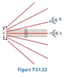
Young’s double-slit experiment underlies the instrument landing system used to guide aircraft to sale landings at some airports when the visibility is pool. Although real systems are more complicated than the example described here, they operate on the same principles. A pilot is trying to align her plane with a runway as suggested in Figure P37.22. Two radio antennas (the black dots in the figure) are positioned adjacent to the runway, separated by d = 40.0 m. The antennas broadcast unmodulated coherent radio waves at .10.0 MHz.
The red lines in Figure P37.22 represent paths along which maxima in the interference pattern of the radio waves exist. (a) Find the wavelength of the waves. The pilot “locks onto” the strong signal radiated along an interference maximum and steers the plane to keep the received signal strong. If she has found the central maximum, the plane will have precisely the correct heading to land when it reaches the runway as exhibited by plane A. (b) What If? Suppose the plane is living along the first side maximum instead as is the case for plane B. How far to the side of the runway centerline will the plane be when it is 2.00 km from the antennas, measured along its direction of travel? (c) It is possible to tell the pilot that she is on the wrong maximum by sending out two signals from each antenna and equipping the aircraft with a two-channel receiver. The ratio of the two frequencies must not be the ratio of small integers (such as

Trending nowThis is a popular solution!

Chapter 37 Solutions
Physics for Scientists and Engineers, Technology Update, Hybrid Edition (with Enhanced WebAssign Multi-Term LOE Printed Access Card for Physics)


- Table P35.80 presents data gathered by students performing a double-slit experiment. The distance between the slits is 0.0700 mm, and the distance to the screen is 2.50 m. The intensity of the central maximum is 6.50 106 W/m2. What is the intensity at y = 0.500 cm? TABLE P35.80arrow_forwardCoherent light rays of wavelength strike a pair of slits separated by distance d at an angle 1, with respect to the normal to the plane containing the slits as shown in Figure P27.14. The rays leaving the slits make an angle 2 with respect to the normal, and an interference maximum is formed by those rays on a screen that is a great distance from the slits. Show that the angle 2 is given by 2=sin1(sin1md) where m is an integer.arrow_forwardIn the double-slit arrangement of Figure P36.13, d = 0.150 mm, L = 140 cm, = 643 nm. and y = 1.80 cm. (a) What is the path difference for the rays from the two slits arriving at P? (b) Express this path difference in terms of . (c) Does P correspond to a maximum, a minimum, or an intermediate condition? Give evidence for your answer. Figure P36.13arrow_forward
- A beam of 580-nm light passes through two closely spaced glass plates at close to normal incidence as shown in Figure P27.23. For what minimum nonzero value of the plate separation d is the transmitted light bright?arrow_forwardCoherent light rays of wavelength strike a pair of slits separated by distance d at an angle 1 with respect to the normal to the plane containing the slits as shown in Figure P36.9. The rays leaving the slits make an angle 2 with respect to the normal, and an interference maximum is formed by those rays on a screen that is a great distance from the slits. Show that the angle 2 is given by 2=sin1(sin1md) where m is an integer. Figure P36.9arrow_forwardFigure CQ27.4 shows an unbroken soap film in a circular frame. The film thickness increases from top to bottom, slowly at first and then rapidly. As a simpler model, consider a soap film (n = 1.33) contained within a rectangular wire frame. The frame is held vertically so that the film drains downward and forms a wedge with flat faces. The thickness of the film at the top is essentially zero. The film is viewed in reflected white light with near-normal incidence, and the first violet ( = 420 nm) interference band is observed 3.00 cm from the top edge of the film. (a) Locate the first red ( = 680 nm) interference band. (b) Determine the film thickness at the positions of the violet and red bands. (c) What is the wedge angle of the film?arrow_forward
- In Figure P27.7 (not to scale), let L = 1.20 m and d = 0.120 mm and assume the slit system is illuminated with monochromatic 500-nm light. Calculate the phase difference between the two wave fronts arriving at P when (a) = 0.500 and (b) y = 5.00 mm. (c) What is the value of for which the phase difference is 0.333 rad? (d) What is the value of for which the path difference is /4?arrow_forwardProblems 49 and 50 are paired. C Optical flats are flat pieces of glass used to determine the flatness of other optical components. They are placed at an angle above the component as shown in Figure P36.49A, and monochromatic light is incident and observed from above, leading to interference fringes. Parts B and C of Figure P36.49 show the results of tests on two optical components. Which of the two is more flat? Explain. Figure P36.49 Problems 49 and 50.arrow_forwardFigure P35.24 shows the diffraction patterns produced by a slit of varying width. What is the relative width of the slit in each case, from narrowest to widest? FIGURE P35.24 Problems 24 and 32.arrow_forward
- Consider the double-slit arrangement shown in Figure P37.60, where the slit separation is d and the distance from the slit to the screen is L. A sheet of transparent plastic having an index of refraction n and thickness t is placed over the upper slit. As a result, the central maximum of the interference pattern moves upward a distance y Find y.arrow_forwardImpressionist painter Georges Seurat created paintings with an enormous number of dots of pure pigment, each of which was approximately 2.00 mm in diameter. The idea was to have colors such as red and green next to each other to form a scintillating canvas, such as in his masterpiece, A Sunday Afternoon on the Island of La Grande Jatte (Fig. P37.15). Assume = 500 nm and a pupil diameter of 5.00 mm. Beyond what distance would a viewer be unable to discern individual dots on the canvas? Figure P37.15arrow_forwardInterference effects are produced at point P on a screen as a result of direct rays from a 5.00 x 10² - nm source and reflected rays off a mirror, as shown in Figure P24.67. If the source is L = 1.00 x 10² m to the left of the screen and h = 1.00 cm above the mirror, find the distance y (in millimeters) to the first dark band above the mirror.arrow_forward
 Principles of Physics: A Calculus-Based TextPhysicsISBN:9781133104261Author:Raymond A. Serway, John W. JewettPublisher:Cengage Learning
 Physics for Scientists and Engineers with Modern ...PhysicsISBN:9781337553292Author:Raymond A. Serway, John W. JewettPublisher:Cengage Learning
 Physics for Scientists and EngineersPhysicsISBN:9781337553278Author:Raymond A. Serway, John W. JewettPublisher:Cengage Learning
 Physics for Scientists and Engineers: Foundations...PhysicsISBN:9781133939146Author:Katz, Debora M.Publisher:Cengage Learning
 Physics for Scientists and Engineers, Technology ...PhysicsISBN:9781305116399Author:Raymond A. Serway, John W. JewettPublisher:Cengage Learning