
MECH ENGINEERING DESIGN(LL)+ACCESS
10th Edition
ISBN: 9781260113952
Author: BUDYNAS
Publisher: MCG
expand_more
expand_more
format_list_bulleted
Videos
Textbook Question
Chapter 4, Problem 107P
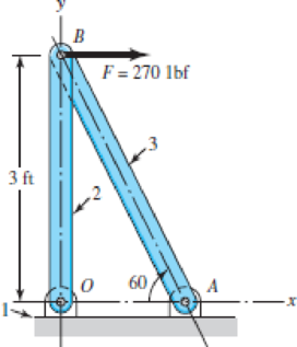
Link 3, shown schematically in the figure, acts as a brace to support the 270-lbf load. For buckling in the plane of the figure, the link may be regarded as pinned at both ends. For out-of-plane buckling, the ends are fixed. Select a suitable material and a method of manufacture, such as forging, casting, stamping, or machining, for casual applications of the brace in oil-field machinery. Specify the dimensions of the cross section as well as the ends so as to obtain a strong, safe, well-made, and economical brace.
Problem 4–107
Expert Solution & Answer
Want to see the full answer?
Check out a sample textbook solution
Chapter 4 Solutions
MECH ENGINEERING DESIGN(LL)+ACCESS
Ch. 4 - The figure shows a torsion bar OA fixed at O,...Ch. 4 - For Prob. 41, if the simple support at point A...Ch. 4 - A torsion-bar spring consists of a prismatic bar,...Ch. 4 - An engineer is forced by geometric considerations...Ch. 4 - A bar in tension has a circular cross section and...Ch. 4 - Prob. 6PCh. 4 - Prob. 7PCh. 4 - Derive the equations given for beam 2 in Table A9...Ch. 4 - Derive the equations given for beam 5 in Table A9...Ch. 4 - The figure shows a cantilever consisting of steel...
Ch. 4 - A simply supported beam loaded by two forces is...Ch. 4 - Using superposition, find the deflection of the...Ch. 4 - A rectangular steel bar supports the two...Ch. 4 - An aluminum tube with outside diameter of 2 in and...Ch. 4 - The cantilever shown in the figure consists of two...Ch. 4 - Using superposition for the bar shown, determine...Ch. 4 - A simply supported beam has a concentrated moment...Ch. 4 - Prob. 18PCh. 4 - Using the results of Prob. 418, use superposition...Ch. 4 - Prob. 20PCh. 4 - Consider the uniformly loaded simply supported...Ch. 4 - Prob. 22PCh. 4 - Prob. 23PCh. 4 - Prob. 24PCh. 4 - Prob. 25PCh. 4 - Prob. 26PCh. 4 - Prob. 27PCh. 4 - Prob. 28PCh. 4 - 429 to 434 For the steel countershaft specified in...Ch. 4 - Prob. 30PCh. 4 - Prob. 31PCh. 4 - Prob. 32PCh. 4 - For the steel countershaft specified in the table,...Ch. 4 - For the steel countershaft specified in the table,...Ch. 4 - Prob. 35PCh. 4 - Prob. 36PCh. 4 - Prob. 37PCh. 4 - Prob. 38PCh. 4 - Prob. 39PCh. 4 - Prob. 40PCh. 4 - The cantilevered handle in the figure is made from...Ch. 4 - Prob. 42PCh. 4 - The cantilevered handle in Prob. 384, p. 154, is...Ch. 4 - A flat-bed trailer is to be designed with a...Ch. 4 - The designer of a shaft usually has a slope...Ch. 4 - Prob. 46PCh. 4 - If the diameter of the steel beam shown is 1.25...Ch. 4 - For the beam of Prob. 4-47, plot the magnitude of...Ch. 4 - Prob. 49PCh. 4 - 4-50 and 4-51 The figure shows a rectangular...Ch. 4 - and 451 the ground at one end and supported by a...Ch. 4 - The figure illustrates a stepped torsion-bar...Ch. 4 - Consider the simply supported beam 5 with a center...Ch. 4 - Prob. 54PCh. 4 - Prob. 55PCh. 4 - Solve Prob. 410 using singularity functions. Use...Ch. 4 - Prob. 57PCh. 4 - Prob. 58PCh. 4 - Prob. 59PCh. 4 - Solve Prob. 413 using singularity functions. Since...Ch. 4 - Prob. 61PCh. 4 - Solve Prob. 419 using singularity functions to...Ch. 4 - Using singularity functions, write the deflection...Ch. 4 - Determine the deflection equation for the...Ch. 4 - Use Castiglianos theorem to verify the maximum...Ch. 4 - Use Castiglianos theorem to verify the maximum...Ch. 4 - Solve Prob. 415 using Castiglianos theorem.Ch. 4 - Solve Prob. 452 using Castiglianos theoremCh. 4 - Determine the deflection at midspan for the beam...Ch. 4 - Using Castiglianos theorem, determine the...Ch. 4 - Solve Prob. 441 using Castiglianos theorem. Since...Ch. 4 - Solve Prob. 442 using Castiglianos theorem.Ch. 4 - The cantilevered handle in Prob. 384 is made from...Ch. 4 - Solve Prob. 450 using Castiglianos theorem.Ch. 4 - Solve Prob. 451 using Castiglianos theorem.Ch. 4 - The steel curved bar shown has a rectangular cross...Ch. 4 - Repeat Prob. 476 to find the vertical deflection...Ch. 4 - For the curved steel beam shown. F = 6.7 kips....Ch. 4 - A steel piston ring has a mean diameter of 70 mm....Ch. 4 - For the steel wire form shown, use Castiglianos...Ch. 4 - 4-81 and 4-82 The part shown is formed from a...Ch. 4 - 4-81 and 4-82 The part shown is formed from a...Ch. 4 - Repeat Prob. 481 for the vertical deflection at...Ch. 4 - Repeat Prob. 482 for the vertical deflection at...Ch. 4 - A hook is formed from a 2-mm-diameter steel wire...Ch. 4 - The figure shows a rectangular member OB, made...Ch. 4 - Prob. 87PCh. 4 - For the wire form shown, determine the deflection...Ch. 4 - Prob. 89PCh. 4 - Prob. 90PCh. 4 - Prob. 91PCh. 4 - Prob. 92PCh. 4 - Solve Prob. 492 using Castiglianos method and...Ch. 4 - An aluminum step bar is loaded as shown. (a)...Ch. 4 - The steel shaft shown in the figure is subjected...Ch. 4 - Repeat Prob. 495 with the diameters of section OA...Ch. 4 - The figure shows a 12- by 1-in rectangular steel...Ch. 4 - For the beam shown, determine the support...Ch. 4 - Solve Prob. 498 using Castiglianos theorem and...Ch. 4 - Consider beam 13 in Table A9, but with flexible...Ch. 4 - Prob. 101PCh. 4 - The steel beam ABCD shown is simply supported at C...Ch. 4 - Prob. 103PCh. 4 - A round tubular column has outside and inside...Ch. 4 - For the conditions of Prob. 4104, show that...Ch. 4 - Link 2, shown in the figure, is 25 mm wide, has...Ch. 4 - Link 3, shown schematically in the figure, acts as...Ch. 4 - The hydraulic cylinder shown in the figure has a...Ch. 4 - The figure shows a schematic drawing of a...Ch. 4 - If drawn, a figure for this problem would resemble...Ch. 4 - Design link CD of the hand-operated toggle press...Ch. 4 - Find the maximum values of the spring force and...Ch. 4 - As shown in the figure, the weight W1 strikes W2...Ch. 4 - Part a of the figure shows a weight W mounted...
Knowledge Booster


Learn more about
Need a deep-dive on the concept behind this application? Look no further. Learn more about this topic, mechanical-engineering and related others by exploring similar questions and additional content below.Similar questions
- The piston in an engine is attached to a connecting rod AB, which in turn is connected to a crank arm BC (see figure). The piston slides without friction in a cylinder and is subjected to a force P (assumed to be constant) while moving to the right in the Figure. The connecting rod. with diameter d and length L, is attached at both ends by pins. The crank arm rotates about the axle at C with the pin at B moving in a circle of radius R. The axle at C, which is supported by bearings, exerts a resisting moment M against the crank arm. (a) Obtain a formula for the maximum permissible force Pallow. based upon an allowable compressive stress acin the connecting rod. (b) Calculate the Force Pallowfor the following data:arrow_forwardA large precast concrete panel for a warehouse is raised using two sets of cables at two lift lines, as shown in the figure part a. Cable 1 has a length L1 = 22 Ft, cable 2 has a length L2= 10 ft, and the distance along the panel between lift points Band D is d = 14 ft (see figure part b). The total weight of the panel is W = 85 kips. Assuming the cable lift Forces F at each lift line are about equal, use the simplified model of one half of the panel in figure part b to perform your analysis for the lift position shown. Find the required cross-sectional area AC of the cable if its breaking stress is 91 ksi and a factor of safety of 4 with respect to failure is desired.arrow_forwardA steel riser pipe hangs from a drill rig located offshore in deep water (see figure). (a) What is the greatest length (meters) it can have without breaking if the pipe is suspended in the air and the ultimate strength (or breaking strength) is 550 MPa? (b) If the same riser pipe hangs from a drill rig at sea, what is the greatest length? (Obtain the weight densities of steel and sea water from Table M, Appendix I. Neglect the effect of buoyant foam casings on the pipe.)arrow_forward
- A safety valve on the top of a tank containing steam under pressure p has a discharge hole of diameter d(see figure). The valve is designed to release the steam when the pressure reaches the value Pmax If the natural length of the spring, is L and its stiffness is k, what should be the dimension ft of the valve? (Express your result as a formula for h.)arrow_forwardCompare the angle of twist 1 for a thin-walled circular tube (see figure) calculated from the approximate theory for thin-walled bars with the angle of twist 2 calculated from the exact theory of torsion for circular bars, Express the ratio 12terms of the non-dimensional ratio ß = r/t. Calculate the ratio of angles of twist for ß = 5, 10, and 20. What conclusion about the accuracy of the approximate theory do you draw from these results?arrow_forwardThe hoisting arrangement for lifting a large pipe is shown in the figure. The spreader is a steel tubular section with outer diameter 70 mm and inner diameter 57 mm. Its length is 2.6 m, and its modulus of elasticity is 200 GPa. Based upon a factor of safety of 2.25 with respect to Euler buckling of the spreader, what is the maximum weight of pipe that can be lifted? (Assume pinned conditions at the ends of the spreader.)arrow_forward
- A bungee jumper having a mass of 55 kg leaps from a bridge, braking her fall with a long elastic shock cord having axial rigidity EA = 2.3 kN (see figure). If the jumpoff point is 60 m above the water, and if it is desired to maintain a clearance of 10 m between the jumper and the water, what length L of cord should be used?arrow_forward-19 The mechanical assembly shown in the figure consists of an aluminum tube, a rigid end plate, and two steel cables. The slack is removed from the cables by rotating the turnbuckles until the assembly is snug but with no initial stresses. Afterward, the turnbuckles are tightened by 1.5 turns. Calculate the forces in the tube and the cables and determine the shortening of the tube. As= 0.85 in2 for each cable, AA= 4.5 in2, L = 20 in., Es= 29,000 ksi, EA= 10,600 ksi, and p = 1/16 inarrow_forwardA steel cable with a nominal diameter of 25 mm (see Table 2-1) is used in a construction yard to lift a bridge section weighing 38 kN. as shown in the figure. The cable has an effective modulus of elasticity E = 140 GPa. (a) If the cable is 14 m long, how much will it stretch when the load is picked up? (b) If the cable is rated for a maximum load of 70 kN, that is the factor of safety with respect to failure of the cable?arrow_forward
- A polyethylene tube (length L) has a cap that when installed compresses a spring (with under-formed length L1) by an amount ?? = (L1 = L). Ignore deformations of the cap and base. Use the force at the base of the spring as the redundant. Use numerical properties given in the boxes. (a) What is the resulting Force-in the spring, Fk? (b) What is the resulting Force in the tube, Ftl (c) What is the filial length of the tube, Lf? (d) What temperature change ?T inside the tube will result in zero force in the springarrow_forwardA long re Lai nine: wall is braced by wood shores set at an angle of 30° and supported by concrete thrust blocks, as shown in the first part of the figure. The shores are evenly spaced at 3 m apart. For analysis purposes, the wall and shores are idealized as shown in the second part of the figure. Note that the base of the wall and both ends of the shores are assumed to be pinned. The pressure of the soil against the wall is assumed to be triangularly distributed, and the resultant force acting on a 3-meter length of the walls is F = 190 kN. If each shore has a 150 mm X 150 mm square cross section, what is the compressive stressarrow_forwardAn idealized column is composed of rigid bars ABC and CD joined by an elastic connection with rotational stiffness ßRIat C. There is a roller support at B and an elastic support at D with translationa1 spring stiffness ß and rotational stiffness ßR2. Find the critical buckling loads for each of the two buckling modes of the column. Assume that L = 3 m, ß = 9 kN/m, and ßR]= ßR1= ßL2. Sketch the buckled mode shapes.arrow_forward
arrow_back_ios
SEE MORE QUESTIONS
arrow_forward_ios
Recommended textbooks for you
 Mechanics of Materials (MindTap Course List)Mechanical EngineeringISBN:9781337093347Author:Barry J. Goodno, James M. GerePublisher:Cengage Learning
Mechanics of Materials (MindTap Course List)
Mechanical Engineering
ISBN:9781337093347
Author:Barry J. Goodno, James M. Gere
Publisher:Cengage Learning
Physics 33 - Fluid Statics (1 of 10) Pressure in a Fluid; Author: Michel van Biezen;https://www.youtube.com/watch?v=mzjlAla3H1Q;License: Standard YouTube License, CC-BY