
MECH ENGINEERING DESIGN(LL)+ACCESS
10th Edition
ISBN: 9781260113952
Author: BUDYNAS
Publisher: MCG
expand_more
expand_more
format_list_bulleted
Videos
Textbook Question
Chapter 4, Problem 88P
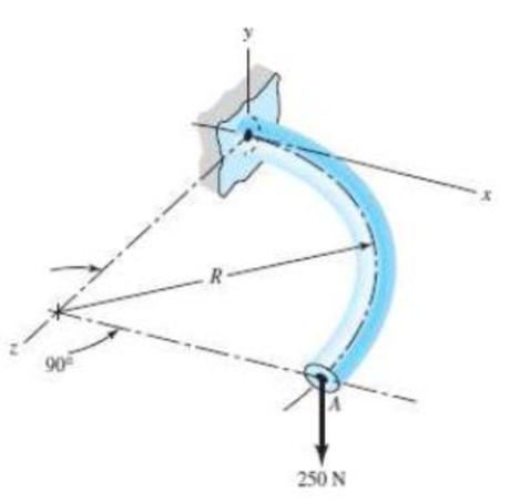
For the wire form shown, determine the deflection of point A in the y direction. Assume R/h.> 10 and consider the effects of bending and torsion only. The wire is steel with E = 200 GPa, v = 0.29, and has a diameter of 6 mm. Before application of the 250-N force the wire form is in the xz plane where the radius R is 80 mm.
Expert Solution & Answer
Want to see the full answer?
Check out a sample textbook solution
Students have asked these similar questions
Two elastic beams with equal bending rigidity of EI are connected by a pin at B. The beam is fixed at A and a roller support is attached at C. Beam BC is subjected to a uniformly distributed load of magnitude w=1 N/m. If the bending rigidity EI is 108Nmm2, determine
a) the lateral deflection at B,
b) the rotational angle at B,
c) the rotational angle at C.
d) sketch the deformed shape
Using Castigliano’s theorem, determine horizontal and vertical components of deflection at point C.
Given: P=1000 N
EA= 2*10^6 N
Find the deflection at D relative to point A of the copper bar. Assume the material behaves elastically. E = 15 x 103 ksi
...
Chapter 4 Solutions
MECH ENGINEERING DESIGN(LL)+ACCESS
Ch. 4 - The figure shows a torsion bar OA fixed at O,...Ch. 4 - For Prob. 41, if the simple support at point A...Ch. 4 - A torsion-bar spring consists of a prismatic bar,...Ch. 4 - An engineer is forced by geometric considerations...Ch. 4 - A bar in tension has a circular cross section and...Ch. 4 - Prob. 6PCh. 4 - Prob. 7PCh. 4 - Derive the equations given for beam 2 in Table A9...Ch. 4 - Derive the equations given for beam 5 in Table A9...Ch. 4 - The figure shows a cantilever consisting of steel...
Ch. 4 - A simply supported beam loaded by two forces is...Ch. 4 - Using superposition, find the deflection of the...Ch. 4 - A rectangular steel bar supports the two...Ch. 4 - An aluminum tube with outside diameter of 2 in and...Ch. 4 - The cantilever shown in the figure consists of two...Ch. 4 - Using superposition for the bar shown, determine...Ch. 4 - A simply supported beam has a concentrated moment...Ch. 4 - Prob. 18PCh. 4 - Using the results of Prob. 418, use superposition...Ch. 4 - Prob. 20PCh. 4 - Consider the uniformly loaded simply supported...Ch. 4 - Prob. 22PCh. 4 - Prob. 23PCh. 4 - Prob. 24PCh. 4 - Prob. 25PCh. 4 - Prob. 26PCh. 4 - Prob. 27PCh. 4 - Prob. 28PCh. 4 - 429 to 434 For the steel countershaft specified in...Ch. 4 - Prob. 30PCh. 4 - Prob. 31PCh. 4 - Prob. 32PCh. 4 - For the steel countershaft specified in the table,...Ch. 4 - For the steel countershaft specified in the table,...Ch. 4 - Prob. 35PCh. 4 - Prob. 36PCh. 4 - Prob. 37PCh. 4 - Prob. 38PCh. 4 - Prob. 39PCh. 4 - Prob. 40PCh. 4 - The cantilevered handle in the figure is made from...Ch. 4 - Prob. 42PCh. 4 - The cantilevered handle in Prob. 384, p. 154, is...Ch. 4 - A flat-bed trailer is to be designed with a...Ch. 4 - The designer of a shaft usually has a slope...Ch. 4 - Prob. 46PCh. 4 - If the diameter of the steel beam shown is 1.25...Ch. 4 - For the beam of Prob. 4-47, plot the magnitude of...Ch. 4 - Prob. 49PCh. 4 - 4-50 and 4-51 The figure shows a rectangular...Ch. 4 - and 451 the ground at one end and supported by a...Ch. 4 - The figure illustrates a stepped torsion-bar...Ch. 4 - Consider the simply supported beam 5 with a center...Ch. 4 - Prob. 54PCh. 4 - Prob. 55PCh. 4 - Solve Prob. 410 using singularity functions. Use...Ch. 4 - Prob. 57PCh. 4 - Prob. 58PCh. 4 - Prob. 59PCh. 4 - Solve Prob. 413 using singularity functions. Since...Ch. 4 - Prob. 61PCh. 4 - Solve Prob. 419 using singularity functions to...Ch. 4 - Using singularity functions, write the deflection...Ch. 4 - Determine the deflection equation for the...Ch. 4 - Use Castiglianos theorem to verify the maximum...Ch. 4 - Use Castiglianos theorem to verify the maximum...Ch. 4 - Solve Prob. 415 using Castiglianos theorem.Ch. 4 - Solve Prob. 452 using Castiglianos theoremCh. 4 - Determine the deflection at midspan for the beam...Ch. 4 - Using Castiglianos theorem, determine the...Ch. 4 - Solve Prob. 441 using Castiglianos theorem. Since...Ch. 4 - Solve Prob. 442 using Castiglianos theorem.Ch. 4 - The cantilevered handle in Prob. 384 is made from...Ch. 4 - Solve Prob. 450 using Castiglianos theorem.Ch. 4 - Solve Prob. 451 using Castiglianos theorem.Ch. 4 - The steel curved bar shown has a rectangular cross...Ch. 4 - Repeat Prob. 476 to find the vertical deflection...Ch. 4 - For the curved steel beam shown. F = 6.7 kips....Ch. 4 - A steel piston ring has a mean diameter of 70 mm....Ch. 4 - For the steel wire form shown, use Castiglianos...Ch. 4 - 4-81 and 4-82 The part shown is formed from a...Ch. 4 - 4-81 and 4-82 The part shown is formed from a...Ch. 4 - Repeat Prob. 481 for the vertical deflection at...Ch. 4 - Repeat Prob. 482 for the vertical deflection at...Ch. 4 - A hook is formed from a 2-mm-diameter steel wire...Ch. 4 - The figure shows a rectangular member OB, made...Ch. 4 - Prob. 87PCh. 4 - For the wire form shown, determine the deflection...Ch. 4 - Prob. 89PCh. 4 - Prob. 90PCh. 4 - Prob. 91PCh. 4 - Prob. 92PCh. 4 - Solve Prob. 492 using Castiglianos method and...Ch. 4 - An aluminum step bar is loaded as shown. (a)...Ch. 4 - The steel shaft shown in the figure is subjected...Ch. 4 - Repeat Prob. 495 with the diameters of section OA...Ch. 4 - The figure shows a 12- by 1-in rectangular steel...Ch. 4 - For the beam shown, determine the support...Ch. 4 - Solve Prob. 498 using Castiglianos theorem and...Ch. 4 - Consider beam 13 in Table A9, but with flexible...Ch. 4 - Prob. 101PCh. 4 - The steel beam ABCD shown is simply supported at C...Ch. 4 - Prob. 103PCh. 4 - A round tubular column has outside and inside...Ch. 4 - For the conditions of Prob. 4104, show that...Ch. 4 - Link 2, shown in the figure, is 25 mm wide, has...Ch. 4 - Link 3, shown schematically in the figure, acts as...Ch. 4 - The hydraulic cylinder shown in the figure has a...Ch. 4 - The figure shows a schematic drawing of a...Ch. 4 - If drawn, a figure for this problem would resemble...Ch. 4 - Design link CD of the hand-operated toggle press...Ch. 4 - Find the maximum values of the spring force and...Ch. 4 - As shown in the figure, the weight W1 strikes W2...Ch. 4 - Part a of the figure shows a weight W mounted...
Knowledge Booster


Learn more about
Need a deep-dive on the concept behind this application? Look no further. Learn more about this topic, mechanical-engineering and related others by exploring similar questions and additional content below.Similar questions
- ‘11.5-2 A steel bar having a square cross section (50 mm × 50 mm)and length L = 2.0 in is compressed by axial loads that have a resultant P = 60 kN acting at the midpoint of one side of the cross section (sec figure). Assuming that the modulus of elasticity £is equal to 210 GPa and that the ends of the bar are pinned, calculate the maximum deflection S and the maximum bending moment Mmax.arrow_forward-33 Find the horizontal deflection hand verti cal deflection vat the free end C of the frame ABC shown in the figure. (The flexural rigidity EI is con stant throughout the frame.) Note: Disregard the effects of axial deformations and consider only the effects of bending due to the load P.arrow_forwardA horizontal load P acts at end C of the bracket ABC shown in the figure. Determine the deflection 6Cof point C. Determine the maximum upward deflection 8 of member AB. Note: Assume that the flexural rigidity EI is constant throughout the frame. Also, disregard the effects of axial deformations and consider only the effects of bending due to the load P.arrow_forward
- Determine the angle of rotation 0Band deflectionarrow_forwardThe cantilever beam ACB shown in the figure supports a uniform load of intensity q throughout its length. The beam has moments of inertia I2and IYin parts AC and CB, respectively. Using the method of superposition, determine the deflection SBat the free end due to the uniform load. Determine the ratio r of the deflection 6Bto the deflection 3Xat the free end of a prismatic cantilever with moment of inertia /] carrying the same load. Plot a graph of the deflection ratio r versus the ratio 12 //t of the moments of inertia. (Let 7, tlxvary from I to 5.)arrow_forwardAn aluminum bar having a rectangular cross section (2.0 in. × 1.0 in.) and length L = 30 in. is compressed by axial loads that have a resultant P = 2800 lb acting at the midpoint of the long side of the cross section (sec figure). Assuming that the modulus of elasticity E is equal to 10 × 106 psi and that the ends of the bar are pinned, calculate the maximum deflection and the maximum bending moment Mmax.arrow_forward
- An overhanging beam ABC of height h has a sliding support at A and a roller at B, The beam is heated to a temperature Tton the top and T2on the bottom (see figure). Determine the equation of the deflection curve of the beam, the angle of rotation 6Cat end C, and the deflection Bfat end C.arrow_forwardA wide-f hinge member (W 10 × 30) is compressed by axial loads that have a resultant P = 20 kips acting at the point shown in the figure. The material is steel with modulus of elasticity E = 29,000 ksi. Assuming pinned-end conditions, determine the maximum permissible length Lmaxif the deflection is not to exceed 1/400th of the length.arrow_forwardDetermine the vertical deflection of point A on the bent cantilever shown in figure below when loaded at A with a vertical load of 25 N. The cantilever is built in at B, and EI may be taken as constant throughout and equal to 450 N m2.arrow_forward
- In the figure shown, each of the four vertical links connecting the two rigid horizontal members is made of aluminum (E = 70 GPa) and has a uniform rectangular cross section of 10 mm x 40 mm. For the loading shown, determine the deflection and the direction of (a) point E, (b) point F, (c) point G. Show FBD and complete process.arrow_forwardDetermine the deflection at point C and at the site of action of the load. Take Est = 200 GPa, I = 17 x 106 mm4. Neglect the mass of the steel beam.arrow_forwardA force tangent to 1.75 feet diameter pulley is 5200 N and is mounted on a 2 inches shaft. Determine the torsional deflection per meter of length if G = 83 x 106 Kpa.arrow_forward
arrow_back_ios
SEE MORE QUESTIONS
arrow_forward_ios
Recommended textbooks for you
 Mechanics of Materials (MindTap Course List)Mechanical EngineeringISBN:9781337093347Author:Barry J. Goodno, James M. GerePublisher:Cengage Learning
Mechanics of Materials (MindTap Course List)
Mechanical Engineering
ISBN:9781337093347
Author:Barry J. Goodno, James M. Gere
Publisher:Cengage Learning
Mechanical SPRING DESIGN Strategy and Restrictions in Under 15 Minutes!; Author: Less Boring Lectures;https://www.youtube.com/watch?v=dsWQrzfQt3s;License: Standard Youtube License