
Videos
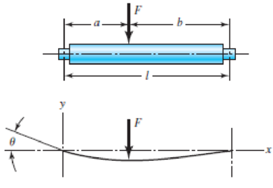
The designer of a shaft usually has a slope constraint imposed by the bearings used. This limit will be denoted as ξ. If the shaft shown in the figure is to have a uniform diameter d except in the locality of the bearing mounting, it can be approximated as a uniform beam with simple supports. Show that the minimum diameters to meet the slope constraints at the left and right bearings are, respectively,
Problem 4–45
Want to see the full answer?
Check out a sample textbook solution
Chapter 4 Solutions
MECH ENGINEERING DESIGN(LL)+ACCESS


- A load of 100 kN, followed by another load of 50 kN, at a distance of 10 metres, advances across a girder with a 100-metre span. Obtain an expression for the maximum bending moment at a section of the girder at a distance of z metres from an abutment. Please provide solutions. Answer is z(140-1.5z) for z< (100/3)m;(100-z)(1.5z-5) for z>(100/3) m.arrow_forwardDraw the shearing-force and bending-moment diagrams for the following beams: 1. A cantilever of length 20 m carrying a load of 10 kN at a distance of 15 m from the supported end. 2. A cantilever of length 20 m carrying a load of 10 kN is uniformly distributed over the inner 15 m of its length. 3. A cantilever of length 12 m carrying a load of 8 kN, applied 5 m from the supported end, and a load of 2kNlm over its whole length.arrow_forwarddetermine the diagram of the shear forces and bending moments in the beam shown below. Data P = 20kN, M = 60kNm, q = 10kN / m, a = 5m, b = 2m, c = 3, alpha = 60.arrow_forward
- Two elastic beams with equal bending rigidity of EI are connected by a pin at B. The beam is fixed at A and a roller support is attached at C. Beam BC is subjected to a uniformly distributed load of magnitude w=1 N/m. If the bending rigidity EI is 108Nmm2, determine a) the lateral deflection at B, b) the rotational angle at B, c) the rotational angle at C. d) sketch the deformed shapearrow_forwardIf the beam has a rectangular cross-section, then the shear-stress distribution will be parabolic. True or False?arrow_forwardThe section modulus for the beam of rectangular cross section of size 50 mm x 40 mm is ______________ mm3.arrow_forward
- The beam is made of four aluminium plates welded together as shown in Figure 1. Knowing that E = 65 GPa and neglecting the effect of the fillet. Determine the corresponding radius of curvature of the beam.arrow_forwardDetermine the vertical deflection of point A on the bent cantilever shown in figure below when loaded at A with a vertical load of 25 N. The cantilever is built in at B, and EI may be taken as constant throughout and equal to 450 N m2.arrow_forwardThe beam cross section shown below has been proposed for a short pedestrian bridge. The cross section will consist of two pipes that are welded to a rectangular web plate. Dimensions of the cross section are: h = 430 mm tw = 16 mm d = 110 mm t = 4.8 mm Additionally: • The area of each pipe is A = 1586 mm2. • The moment of inertia of the entire beam cross section about the z centroidal axis is IZ = 194710000 mm4. If the beam will be subjected to a shear force of V = 170 kN, determine the shear stress at point K, located at yK = 70 mm below the z centroidal axis.arrow_forward
- Beam loaded as shown in Fig. below. Determine the Following: Reaction support at point B. a. 56KN (Downward Direction) b. 56KN (Upward Direction) c. 35KN (Downward Direction) d. 35KN (Upward Direction) Reaction support at point D. a. 26 KN (Downward Direction) b. 26 KN (Upward Direction) c. 24KN (Downward Direction) d. 24KN (Upward Direction) Shear force equation of section AB. a. -30KN b. 30KN c. -32KN d. 32KN Shear force equation of section CD. a. -24KN b. 24KN c. -28KN d. 28KN Bending moment equation of section BC. a. 26KN(x)+56KN.m b. 26KN(x)-56KN.m c. -26KN(x)+56KN.m d. None of the above. Maximum bending moment of the beam. a. 47KN.m b. 46KN.m c. 48KN.m d. None of the abovearrow_forwardThe section modulus for the beam of rectangular cross section of size 80 mm x 85 mm, is ______________ mm3. The section modulus (unit is in mm3)= ______________ Answerarrow_forwarda) 1. The support reaction forces at the A and C, in terms of P,be careful of the sign. 2. Give the expressions of the shear and moment at an arbitrary poistion x of AB segment, in terms of P and x, be careful of the sign. 3. Give the expressions of the shear and moment at an arbitrary poistion x of BC segment, in terms of P and x, be careful of the sign. b)Given l= 1000 mm, P= 4000 N and l1/l=0.66, calculate the internal shear force and draw the moment diagramarrow_forward
 Elements Of ElectromagneticsMechanical EngineeringISBN:9780190698614Author:Sadiku, Matthew N. O.Publisher:Oxford University Press
 Mechanics of Materials (10th Edition)Mechanical EngineeringISBN:9780134319650Author:Russell C. HibbelerPublisher:PEARSON
 Thermodynamics: An Engineering ApproachMechanical EngineeringISBN:9781259822674Author:Yunus A. Cengel Dr., Michael A. BolesPublisher:McGraw-Hill Education
 Control Systems EngineeringMechanical EngineeringISBN:9781118170519Author:Norman S. NisePublisher:WILEY
 Mechanics of Materials (MindTap Course List)Mechanical EngineeringISBN:9781337093347Author:Barry J. Goodno, James M. GerePublisher:Cengage Learning
 Engineering Mechanics: StaticsMechanical EngineeringISBN:9781118807330Author:James L. Meriam, L. G. Kraige, J. N. BoltonPublisher:WILEY