
Basic Engineering Circuit Analysis
11th Edition
ISBN: 9781118539293
Author: J. David Irwin, R. Mark Nelms
Publisher: WILEY
expand_more
expand_more
format_list_bulleted
Concept explainers
Videos
Textbook Question
Chapter 4, Problem 14P
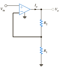
Determine the gain of the amplifier in Fig. P4.14. What is the value of
Expert Solution & Answer
Want to see the full answer?
Check out a sample textbook solution
Students have asked these similar questions
4.31 Determine the current io flowing into the op-amp of thecircuit in Fig. P4.29 under the conditions Vs = 0.5 V, V0 = 0 V,and RL = 10 k Ohms
A battery-powered C-E amplifier is operating from a single 1.5-V battery. Estimate its voltage gain. What will the gain be if the battery voltage dropsto 1 V?
(a) Find the Q-point for the transistor in the circuit in Fig. P4.114(a) if V DD =+12 V. (b) Repeat for the circuit in Fig. 4.114(b)
Chapter 4 Solutions
Basic Engineering Circuit Analysis
Ch. 4 - An amplifier has a gain of 15 and the input...Ch. 4 - An amplifier has a gain of 5 and the output...Ch. 4 - An op-amp based amplifier has supply voltages of...Ch. 4 - For an ideal op-amp, the voltage gain and input...Ch. 4 - Revisit your answers in Problem 4.4 under the...Ch. 4 - Revisit the exact analysis of the inverting...Ch. 4 - Revisit the exact analysis of the inverting...Ch. 4 - An op-amp based amplifier has 18V supplies and a...Ch. 4 - Assuming an ideal op-amp, determine the voltage...Ch. 4 - Assuming an ideal op-amp, determine the voltage...
Ch. 4 - Assuming an ideal op-amp in Fig. P4.11, determine...Ch. 4 - Assuming an ideal op-amp, find the voltage gain of...Ch. 4 - Assuming an ideal op-amp in Fig. P4.13, determine...Ch. 4 - Determine the gain of the amplifier in Fig. P4.14....Ch. 4 - For the amplifier in Fig. P4.15, find the gain and...Ch. 4 - Using the ideal op-amp assumptions, determine the...Ch. 4 - Using the ideal op-amp assumptions, determine...Ch. 4 - In a useful application, the amplifier drives a...Ch. 4 - The op-amp in the amplifier in Fig. P4.19 operates...Ch. 4 - For the amplifier in Fig. P4.20, the maximum value...Ch. 4 - For the circuit in Fig. P4.21, (a) find Vo in...Ch. 4 - Find Vo in the circuit in Fig. P4.22, assuming...Ch. 4 - The network in Fig. P4.23 is a current-to-voltage...Ch. 4 - Prob. 24PCh. 4 - Determine the relationship between v1 and io in...Ch. 4 - Find Vo in the network in Fig. P4.26 and explain...Ch. 4 - Determine the expression for vo in the network in...Ch. 4 - Show that the output of the circuit in Fig. P4.28...Ch. 4 - Find vo in the network in Fig. P4.29.Ch. 4 - Find the voltage gain of the op-amp circuit shown...Ch. 4 - Determine the relationship between and in the...Ch. 4 - Prob. 32PCh. 4 - For the circuit in Fig. P4.33, find the value of...Ch. 4 - Find Vo in the circuit in Fig. P4.34.Ch. 4 - Find Vo in the circuit in Fig. P4.35.Ch. 4 - Determine the expression for the output voltage,...Ch. 4 - Determine the output voltage, of the noninverting...Ch. 4 - Find the input/output relationship for the current...Ch. 4 - Find V0 in the circuit in Fig. P4.39.Ch. 4 - Find Vo in the circuit in Fig. P4.40.Ch. 4 - Find the expression for in the differential...Ch. 4 - Find vo in the circuit in Fig. P4.42.Ch. 4 - Find the output voltage, vo, in the circuit in...Ch. 4 - The electronic ammeter in Example 4.7 has been...Ch. 4 - Given the summing amplifier shown in Fig. 4PFE-l,...Ch. 4 - Determine the output voltage V0 of the summing...Ch. 4 - What is the output voltage V0 in Fig. 4PFE-3. a....Ch. 4 - What value of Rf in the op-amp circuit of Fig....Ch. 4 - What is the voltage Vo in the circuit in Fig....
Knowledge Booster


Learn more about
Need a deep-dive on the concept behind this application? Look no further. Learn more about this topic, electrical-engineering and related others by exploring similar questions and additional content below.Similar questions
- as ap q4barrow_forwardWhat would be the Q-point currents in M4 and M5 in the amplifier as shown if VDD = VSS = 16 V, I2 = 250 μA, RG = 7 kΩ, RL = 2 kΩ, and VT N = 0.75 V, VT P = −0.75 V, Kn = 5 mA/V2, and Kp = 2 mA/V2?arrow_forwardFind the value of R1 required so that the amp has gain, G= -8.24 given R2=560kΩarrow_forward
- For the unity feedback system shown in Fig. Q4(b), where:arrow_forwardWhat are the output current and output resistance of the current source as shown if VDD = 10 V, R4 = 2 MΩ, R3 = 1 MΩ, RS = 120 kΩ, Kp = 750 μA/V2, VT P = −0.75 V, and λ = 0.01 V−1?arrow_forwardA C-S amplifier is operating from a single 15-V supply with VGS −VT N = 1 V. Estimate its voltage gain.arrow_forward
- Figure 4 shows the amplifier circuit with a voltage divider. Find etc ,VC, and, VCEQ,IBQ,ICQ,IEQ ,Av values by analyzing the DC of the circuit.arrow_forwardAn amplifier is required with a voltage gain of 1000 and will be designed using a cascade of several C-S amplifier stages operating from a single 12-V power supply. Estimate the minimum number of amplifier stages required to achieve this gain.arrow_forwardThe figure below shows an inverting amplifier connected to a load RL. Determine the power gain of the amplifier. power gain for the amplifier, G, is defined as the power ratio that reaches the load RL versus the power supplied by the source VS.arrow_forward
- P4ohm using SPT and Thevenin's Theoremarrow_forwardFind the gain (Vout / Vin) of the circuit below. Note: VB voltage source is a DC source and do not neglect the resistance ro.arrow_forwardWhat are the gain Av, input resistance, and output resistance of the three stage amplifier as shown (a) if R2 = 68 kΩ and R1 = 2.7 kΩ?arrow_forward
arrow_back_ios
SEE MORE QUESTIONS
arrow_forward_ios
Recommended textbooks for you
 Introductory Circuit Analysis (13th Edition)Electrical EngineeringISBN:9780133923605Author:Robert L. BoylestadPublisher:PEARSON
 Delmar's Standard Textbook Of ElectricityElectrical EngineeringISBN:9781337900348Author:Stephen L. HermanPublisher:Cengage Learning
 Programmable Logic ControllersElectrical EngineeringISBN:9780073373843Author:Frank D. PetruzellaPublisher:McGraw-Hill Education
 Fundamentals of Electric CircuitsElectrical EngineeringISBN:9780078028229Author:Charles K Alexander, Matthew SadikuPublisher:McGraw-Hill Education
 Electric Circuits. (11th Edition)Electrical EngineeringISBN:9780134746968Author:James W. Nilsson, Susan RiedelPublisher:PEARSON
 Engineering ElectromagneticsElectrical EngineeringISBN:9780078028151Author:Hayt, William H. (william Hart), Jr, BUCK, John A.Publisher:Mcgraw-hill Education,
Introductory Circuit Analysis (13th Edition)
Electrical Engineering
ISBN:9780133923605
Author:Robert L. Boylestad
Publisher:PEARSON
Delmar's Standard Textbook Of Electricity
Electrical Engineering
ISBN:9781337900348
Author:Stephen L. Herman
Publisher:Cengage Learning
Programmable Logic Controllers
Electrical Engineering
ISBN:9780073373843
Author:Frank D. Petruzella
Publisher:McGraw-Hill Education
Fundamentals of Electric Circuits
Electrical Engineering
ISBN:9780078028229
Author:Charles K Alexander, Matthew Sadiku
Publisher:McGraw-Hill Education
Electric Circuits. (11th Edition)
Electrical Engineering
ISBN:9780134746968
Author:James W. Nilsson, Susan Riedel
Publisher:PEARSON
Engineering Electromagnetics
Electrical Engineering
ISBN:9780078028151
Author:Hayt, William H. (william Hart), Jr, BUCK, John A.
Publisher:Mcgraw-hill Education,
What is a Power Amplifier, And Do I Need One?; Author: Sweetwater;https://www.youtube.com/watch?v=2wkmSm4V00M;License: Standard Youtube License