
Basic Engineering Circuit Analysis
11th Edition
ISBN: 9781118539293
Author: J. David Irwin, R. Mark Nelms
Publisher: WILEY
expand_more
expand_more
format_list_bulleted
Concept explainers
Videos
Textbook Question
Chapter 4, Problem 4PFE.1TP
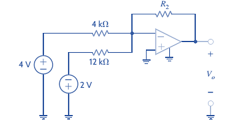
Given the summing amplifier shown in Fig.
a.
b.
Expert Solution & Answer
Want to see the full answer?
Check out a sample textbook solution
Students have asked these similar questions
What would be the Q-point currents in M4 and M5 in the amplifier as shown if VDD = VSS = 16 V, I2 = 250 μA, RG = 7 kΩ, RL = 2 kΩ, and VT N = 0.75 V, VT P = −0.75 V, Kn = 5 mA/V2, and Kp = 2 mA/V2?
Derive the expression for the voltage gain V2/Vg of the circuit in terms of the h parameters.
A battery-powered C-E amplifier is operating from a single 1.5-V battery. Estimate its voltage gain. What will the gain be if the battery voltage dropsto 1 V?
Chapter 4 Solutions
Basic Engineering Circuit Analysis
Ch. 4 - An amplifier has a gain of 15 and the input...Ch. 4 - An amplifier has a gain of 5 and the output...Ch. 4 - An op-amp based amplifier has supply voltages of...Ch. 4 - For an ideal op-amp, the voltage gain and input...Ch. 4 - Revisit your answers in Problem 4.4 under the...Ch. 4 - Revisit the exact analysis of the inverting...Ch. 4 - Revisit the exact analysis of the inverting...Ch. 4 - An op-amp based amplifier has 18V supplies and a...Ch. 4 - Assuming an ideal op-amp, determine the voltage...Ch. 4 - Assuming an ideal op-amp, determine the voltage...
Ch. 4 - Assuming an ideal op-amp in Fig. P4.11, determine...Ch. 4 - Assuming an ideal op-amp, find the voltage gain of...Ch. 4 - Assuming an ideal op-amp in Fig. P4.13, determine...Ch. 4 - Determine the gain of the amplifier in Fig. P4.14....Ch. 4 - For the amplifier in Fig. P4.15, find the gain and...Ch. 4 - Using the ideal op-amp assumptions, determine the...Ch. 4 - Using the ideal op-amp assumptions, determine...Ch. 4 - In a useful application, the amplifier drives a...Ch. 4 - The op-amp in the amplifier in Fig. P4.19 operates...Ch. 4 - For the amplifier in Fig. P4.20, the maximum value...Ch. 4 - For the circuit in Fig. P4.21, (a) find Vo in...Ch. 4 - Find Vo in the circuit in Fig. P4.22, assuming...Ch. 4 - The network in Fig. P4.23 is a current-to-voltage...Ch. 4 - Prob. 24PCh. 4 - Determine the relationship between v1 and io in...Ch. 4 - Find Vo in the network in Fig. P4.26 and explain...Ch. 4 - Determine the expression for vo in the network in...Ch. 4 - Show that the output of the circuit in Fig. P4.28...Ch. 4 - Find vo in the network in Fig. P4.29.Ch. 4 - Find the voltage gain of the op-amp circuit shown...Ch. 4 - Determine the relationship between and in the...Ch. 4 - Prob. 32PCh. 4 - For the circuit in Fig. P4.33, find the value of...Ch. 4 - Find Vo in the circuit in Fig. P4.34.Ch. 4 - Find Vo in the circuit in Fig. P4.35.Ch. 4 - Determine the expression for the output voltage,...Ch. 4 - Determine the output voltage, of the noninverting...Ch. 4 - Find the input/output relationship for the current...Ch. 4 - Find V0 in the circuit in Fig. P4.39.Ch. 4 - Find Vo in the circuit in Fig. P4.40.Ch. 4 - Find the expression for in the differential...Ch. 4 - Find vo in the circuit in Fig. P4.42.Ch. 4 - Find the output voltage, vo, in the circuit in...Ch. 4 - The electronic ammeter in Example 4.7 has been...Ch. 4 - Given the summing amplifier shown in Fig. 4PFE-l,...Ch. 4 - Determine the output voltage V0 of the summing...Ch. 4 - What is the output voltage V0 in Fig. 4PFE-3. a....Ch. 4 - What value of Rf in the op-amp circuit of Fig....Ch. 4 - What is the voltage Vo in the circuit in Fig....
Knowledge Booster


Learn more about
Need a deep-dive on the concept behind this application? Look no further. Learn more about this topic, electrical-engineering and related others by exploring similar questions and additional content below.Similar questions
- An inverting amplifier is shown in Fig. 1(c). The circuit has output voltage –9 V when its input voltage is 2 V. If the load resistance and output current of the amplifier are 2 kN and 2.5 mA respectively, then determine the value of resistances R1 and R2.arrow_forwardA first order amplifier device has a Gain-Bandwidth Product (GBP) of 19MHz. You want to use this device to create an amplifier with a bandwidth of 46kHz. What will the maximum gain of the circuit be in V/V (to one decimal place)? Do not write the units in your answer.arrow_forwardQ4 (A) For the circuit shown in Fig (a) find Rys . (B)A typical transistor amplifieris shown in Fig(b). compute the value of Voarrow_forward
- What are the gain Av, input resistance, and output resistance of the three stage amplifier as shown (a) if R2 = 68 kΩ and R1 = 2.7 kΩ?arrow_forwardDerive the expression for the voltage gain V2/V1 of the circuit in terms of the y parameters.arrow_forwardFind the value of the output voltage for the amplifier shown in the picture below, if the input voltages are V1 = 0.3 V and V2 = -0.4 V. The resistor values are: R1 = 3.3 kΩ, and R2 = 2.9 kΩ and Rf=5.7 kΩ.arrow_forward
- (a) What is the gain of the circuitas shown ifAv = vo/(v1 − v2) and R = 10 k ? (b) What is theinput resistance presented to v2? (c) What is the inputresistance at terminal v1? (d) What is the outputvoltage if v1 = 3 V and v2 = 1.5 cos 8300πt V?(e) What is the output voltage if v1 = [3 −1.5 cos 8300πt] V and v2 = 1.5 sin 8300πt V?arrow_forwardA C-S amplifier is operating from a single 15-V supply with VGS −VT N = 1 V. Estimate its voltage gain.arrow_forwardGiven the summing amplifier shown in Fig. below. Select the value of R2 that will produce an output voltage of –3V.arrow_forward
- Qa) What is the value of ?(∞)?Qb) What is the equation of V1arrow_forwardThe amplifier as shown has R2 = 68 kΩ and R1 = 2.7 kΩ. What are the valuesof Av A, Av B, Av C, RinA, RinB, RinC, and RoutA, RoutB, RoutC, for the amplifier equivalent circuit as shown.arrow_forwardHelping tags: Electrical Engineering . . . WILL UPVOTE, just pls help me answer the question and show complete solutions. Thanks. . . . Find Rb, Ibq, Icq, Vre, Vrc , Vc , Vrb, Vb, Zb, Zin and Zo for the CE amplifier shown in fig.1 Remember Icmax = Vcc/Rc+Re Graph the DC loadline showing the Q point of the circuitarrow_forward
arrow_back_ios
SEE MORE QUESTIONS
arrow_forward_ios
Recommended textbooks for you
 Introductory Circuit Analysis (13th Edition)Electrical EngineeringISBN:9780133923605Author:Robert L. BoylestadPublisher:PEARSON
 Delmar's Standard Textbook Of ElectricityElectrical EngineeringISBN:9781337900348Author:Stephen L. HermanPublisher:Cengage Learning
 Programmable Logic ControllersElectrical EngineeringISBN:9780073373843Author:Frank D. PetruzellaPublisher:McGraw-Hill Education
 Fundamentals of Electric CircuitsElectrical EngineeringISBN:9780078028229Author:Charles K Alexander, Matthew SadikuPublisher:McGraw-Hill Education
 Electric Circuits. (11th Edition)Electrical EngineeringISBN:9780134746968Author:James W. Nilsson, Susan RiedelPublisher:PEARSON
 Engineering ElectromagneticsElectrical EngineeringISBN:9780078028151Author:Hayt, William H. (william Hart), Jr, BUCK, John A.Publisher:Mcgraw-hill Education,
Introductory Circuit Analysis (13th Edition)
Electrical Engineering
ISBN:9780133923605
Author:Robert L. Boylestad
Publisher:PEARSON
Delmar's Standard Textbook Of Electricity
Electrical Engineering
ISBN:9781337900348
Author:Stephen L. Herman
Publisher:Cengage Learning
Programmable Logic Controllers
Electrical Engineering
ISBN:9780073373843
Author:Frank D. Petruzella
Publisher:McGraw-Hill Education
Fundamentals of Electric Circuits
Electrical Engineering
ISBN:9780078028229
Author:Charles K Alexander, Matthew Sadiku
Publisher:McGraw-Hill Education
Electric Circuits. (11th Edition)
Electrical Engineering
ISBN:9780134746968
Author:James W. Nilsson, Susan Riedel
Publisher:PEARSON
Engineering Electromagnetics
Electrical Engineering
ISBN:9780078028151
Author:Hayt, William H. (william Hart), Jr, BUCK, John A.
Publisher:Mcgraw-hill Education,
What is a Power Amplifier, And Do I Need One?; Author: Sweetwater;https://www.youtube.com/watch?v=2wkmSm4V00M;License: Standard Youtube License