
Basic Engineering Circuit Analysis
11th Edition
ISBN: 9781118539293
Author: J. David Irwin, R. Mark Nelms
Publisher: WILEY
expand_more
expand_more
format_list_bulleted
Concept explainers
Videos
Textbook Question
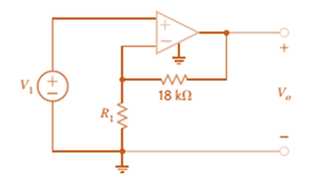
Chapter 4, Problem 33P
For the circuit in Fig. P4.33, find the value of
Expert Solution & Answer
Want to see the full answer?
Check out a sample textbook solution
Students have asked these similar questions
Figure 4 shows the amplifier circuit with a voltage divider. Find etc ,VC, and, VCEQ,IBQ,ICQ,IEQ ,Av values by analyzing the DC of the circuit.
BASIC ELECTRONIC
Given Sketch the drain and transconductance curve for VGS = +2V, +1V, 0V -1V, -2V, -3V and -4V.
For the circuit shown in Fig. P4.1 , (a) Write and verify a gate-level HDL model of the circuit.2. (b) Compare your results with those obtained for Problem 4.1 .
Chapter 4 Solutions
Basic Engineering Circuit Analysis
Ch. 4 - An amplifier has a gain of 15 and the input...Ch. 4 - An amplifier has a gain of 5 and the output...Ch. 4 - An op-amp based amplifier has supply voltages of...Ch. 4 - For an ideal op-amp, the voltage gain and input...Ch. 4 - Revisit your answers in Problem 4.4 under the...Ch. 4 - Revisit the exact analysis of the inverting...Ch. 4 - Revisit the exact analysis of the inverting...Ch. 4 - An op-amp based amplifier has 18V supplies and a...Ch. 4 - Assuming an ideal op-amp, determine the voltage...Ch. 4 - Assuming an ideal op-amp, determine the voltage...
Ch. 4 - Assuming an ideal op-amp in Fig. P4.11, determine...Ch. 4 - Assuming an ideal op-amp, find the voltage gain of...Ch. 4 - Assuming an ideal op-amp in Fig. P4.13, determine...Ch. 4 - Determine the gain of the amplifier in Fig. P4.14....Ch. 4 - For the amplifier in Fig. P4.15, find the gain and...Ch. 4 - Using the ideal op-amp assumptions, determine the...Ch. 4 - Using the ideal op-amp assumptions, determine...Ch. 4 - In a useful application, the amplifier drives a...Ch. 4 - The op-amp in the amplifier in Fig. P4.19 operates...Ch. 4 - For the amplifier in Fig. P4.20, the maximum value...Ch. 4 - For the circuit in Fig. P4.21, (a) find Vo in...Ch. 4 - Find Vo in the circuit in Fig. P4.22, assuming...Ch. 4 - The network in Fig. P4.23 is a current-to-voltage...Ch. 4 - Prob. 24PCh. 4 - Determine the relationship between v1 and io in...Ch. 4 - Find Vo in the network in Fig. P4.26 and explain...Ch. 4 - Determine the expression for vo in the network in...Ch. 4 - Show that the output of the circuit in Fig. P4.28...Ch. 4 - Find vo in the network in Fig. P4.29.Ch. 4 - Find the voltage gain of the op-amp circuit shown...Ch. 4 - Determine the relationship between and in the...Ch. 4 - Prob. 32PCh. 4 - For the circuit in Fig. P4.33, find the value of...Ch. 4 - Find Vo in the circuit in Fig. P4.34.Ch. 4 - Find Vo in the circuit in Fig. P4.35.Ch. 4 - Determine the expression for the output voltage,...Ch. 4 - Determine the output voltage, of the noninverting...Ch. 4 - Find the input/output relationship for the current...Ch. 4 - Find V0 in the circuit in Fig. P4.39.Ch. 4 - Find Vo in the circuit in Fig. P4.40.Ch. 4 - Find the expression for in the differential...Ch. 4 - Find vo in the circuit in Fig. P4.42.Ch. 4 - Find the output voltage, vo, in the circuit in...Ch. 4 - The electronic ammeter in Example 4.7 has been...Ch. 4 - Given the summing amplifier shown in Fig. 4PFE-l,...Ch. 4 - Determine the output voltage V0 of the summing...Ch. 4 - What is the output voltage V0 in Fig. 4PFE-3. a....Ch. 4 - What value of Rf in the op-amp circuit of Fig....Ch. 4 - What is the voltage Vo in the circuit in Fig....
Knowledge Booster


Learn more about
Need a deep-dive on the concept behind this application? Look no further. Learn more about this topic, electrical-engineering and related others by exploring similar questions and additional content below.Similar questions
- What would be the Q-point currents in M4 and M5 in the amplifier as shown if VDD = VSS = 16 V, I2 = 250 μA, RG = 7 kΩ, RL = 2 kΩ, and VT N = 0.75 V, VT P = −0.75 V, Kn = 5 mA/V2, and Kp = 2 mA/V2?arrow_forwardWhat are the output current and output resistance of the current source as shown if VDD = 10 V, R4 = 2 MΩ, R3 = 1 MΩ, RS = 120 kΩ, Kp = 750 μA/V2, VT P = −0.75 V, and λ = 0.01 V−1?arrow_forwardDefinition of the Operational Amplifier. In which cases of circuits types it can be used. List two examples about its application in electrical engineering if there. Show an electrical circuit “figure only” with no calculation, that includes an operational amplifier and explain theoretically its use.arrow_forward
- Suppose we have a resistive load that varies from 5 kΩ to 10 kΩ .We connect this load to an amplifier, and we need the voltage across the load to vary by less than 1 percent with variations in the load resistance. What parameter of the amplifier is important in this situation? What range of values is allowed for the parameter?arrow_forwardWhat would be the currents in Q4 and Q5 in the amplifier as shown if VCC = VEE = 16 V, I2 = 500 μA, RB = 2.7 kΩ, RL = 2 kΩ, and Q3 is modeled by a voltage of VCESAT = 0.2 V in series with a resistance of 50 Ω when it is saturated?arrow_forwardGive an example problem of base resistor biasing with their solution. w/ illustrationarrow_forward
- Subject:Electronics Engineering With a neat circuit diagram, explain the Voltage Divider Bias circuit using approximate analysis. Also derive the equation of stability (S) for Voltage Divider Bias circuit.arrow_forwardDesign a voltage-divider bias network using a supply of 24 V, a transistor with a beta of 110, and an operating point of ICQ = 4 mA and VCEQ = 8 V. Choose VE = 1/8 VCC. * Here designing means find the values of the resistors for the circuit.arrow_forwardfor the collector-feedback configuration of Fig. 4.129, determinearrow_forward
- Find the gain (Vout / Vin) of the circuit below. Note: VB voltage source is a DC source and do not neglect the resistance ro.arrow_forwardThe small-signal model is said to be valid for voltage variations of about 5 mV. To what percentage current change does this correspond? (Consider both positive and negative signals.) What is the maximum allowable voltage signal (positive or negative) if the current change is to be limited to 10%?arrow_forwardSuppose that each output channel of a computer’ssound card can be represented by a 1-V ac sourcein series with a 32-Ω resistor. Each channel ofthe amplifier in the external speakers has an inputresistance of 20 k , and must deliver 10 W intoan 8-Ω speaker. (a) What are the voltage gain, currentgain, and power gain required of the amplifier?(b) What would be a reasonable dc power supplyvoltage for this amplifier?arrow_forward
arrow_back_ios
SEE MORE QUESTIONS
arrow_forward_ios
Recommended textbooks for you
 Introductory Circuit Analysis (13th Edition)Electrical EngineeringISBN:9780133923605Author:Robert L. BoylestadPublisher:PEARSON
 Delmar's Standard Textbook Of ElectricityElectrical EngineeringISBN:9781337900348Author:Stephen L. HermanPublisher:Cengage Learning
 Programmable Logic ControllersElectrical EngineeringISBN:9780073373843Author:Frank D. PetruzellaPublisher:McGraw-Hill Education
 Fundamentals of Electric CircuitsElectrical EngineeringISBN:9780078028229Author:Charles K Alexander, Matthew SadikuPublisher:McGraw-Hill Education
 Electric Circuits. (11th Edition)Electrical EngineeringISBN:9780134746968Author:James W. Nilsson, Susan RiedelPublisher:PEARSON
 Engineering ElectromagneticsElectrical EngineeringISBN:9780078028151Author:Hayt, William H. (william Hart), Jr, BUCK, John A.Publisher:Mcgraw-hill Education,
Introductory Circuit Analysis (13th Edition)
Electrical Engineering
ISBN:9780133923605
Author:Robert L. Boylestad
Publisher:PEARSON
Delmar's Standard Textbook Of Electricity
Electrical Engineering
ISBN:9781337900348
Author:Stephen L. Herman
Publisher:Cengage Learning
Programmable Logic Controllers
Electrical Engineering
ISBN:9780073373843
Author:Frank D. Petruzella
Publisher:McGraw-Hill Education
Fundamentals of Electric Circuits
Electrical Engineering
ISBN:9780078028229
Author:Charles K Alexander, Matthew Sadiku
Publisher:McGraw-Hill Education
Electric Circuits. (11th Edition)
Electrical Engineering
ISBN:9780134746968
Author:James W. Nilsson, Susan Riedel
Publisher:PEARSON
Engineering Electromagnetics
Electrical Engineering
ISBN:9780078028151
Author:Hayt, William H. (william Hart), Jr, BUCK, John A.
Publisher:Mcgraw-hill Education,
What is a Power Amplifier, And Do I Need One?; Author: Sweetwater;https://www.youtube.com/watch?v=2wkmSm4V00M;License: Standard Youtube License