
CODE/MINES MECHANICS MATERIALS >IC<
16th Edition
ISBN: 9781323168950
Author: HIBBELER
Publisher: PEARSON C
expand_more
expand_more
format_list_bulleted
Concept explainers
Videos
Textbook Question
Chapter 4, Problem 4.117RP
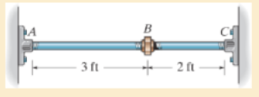
Two A992 steel pipes, each having a cross-sectional area of 0.32 in2, are screwed together using a union at B. Originally the assembly is adjusted so that no load is on the pipe If the union is then tightened so that its screw, having a lead of 0.15 in., undergoes two full turns, determine the average normal stress developed in the pipe. Assume that the union and couplings at A and C are rigid. Neglect the size of the union. Note: The lead would cause the pipe, when unloaded, to shorten 0 15 in when the union is rotated one revolution.
R4–4
Expert Solution & Answer
Want to see the full answer?
Check out a sample textbook solution
Students have asked these similar questions
The bolt has a diameter of 20 (mm) and passes through a tube that has an inner diameter of 50 (mm) and an outer diameter of 60 (mm). If the bolt and tube are made of A-36 steel, determine the normal stress in the tube and bolt when a force of 40 (kN) is applied to the bolt. Assume the end caps are rigid.
The spreader bar is used to lift the 2000-lb tank. Determine the state of stress at points A and B, and indicate the results on a differential volume element.
The three suspender bars AB, CD, and EF are made of A-36 steel (E = 250 MPa) and have equal cross-sectional areas of 400 mm2. Determine the average normal stress in each bar if the rigid beam is subjected to a force of P = 80 kN. Let d = 3 m and L = 8 m
Chapter 4 Solutions
CODE/MINES MECHANICS MATERIALS >IC<
Ch. 4.2 - In each case, determine the internal normal force...Ch. 4.2 - Determine the internal normal force between...Ch. 4.2 - The post weighs 8kN/m. Determine the internal...Ch. 4.2 - The rod is subjected to an external axial force of...Ch. 4.2 - The rigid beam supports the load of 60 kN....Ch. 4.2 - The 20-mm-diameter A-36 steel rod is subjected to...Ch. 4.2 - Segments AB and CD of the assembly are solid...Ch. 4.2 - The 30-mm-diameter A992 steel rod is subjected to...Ch. 4.2 - If the 20-mm-diameter rod is made of A-36 steel...Ch. 4.2 - The 20-mm-diameter 2014-T6 aluminum rod is...
Ch. 4.2 - The 20-mm-diameter 2014-T6 aluminum rod is...Ch. 4.2 - Prob. 4.1PCh. 4.2 - The copper shaft is subjected to the axial loads...Ch. 4.2 - The composite shaft, consisting of aluminum,...Ch. 4.2 - The composite shaft, consisting of aluminum,...Ch. 4.2 - 4-5. The assembly consists of a steel rod CB and...Ch. 4.2 - 4-6. The bar has a cross-sectional area of 3 in2,...Ch. 4.2 - 4–7. If P1 = 50 kip and P2 = 150 kip, determine...Ch. 4.2 - *4-8. If the vertical displacements of end A of...Ch. 4.2 - The assembly consists of two 10-mm diameter red...Ch. 4.2 - The assembly consists of two 10-mm diameter red...Ch. 4.2 - The load is supported by the four 304 stainless...Ch. 4.2 - The load is supported by the four 304 stainless...Ch. 4.2 - The rigid bar is supported by the pin-connected...Ch. 4.2 - Prob. 4.14PCh. 4.2 - Prob. 4.15PCh. 4.2 - *4-16. The hanger consists of three 2014-T6...Ch. 4.2 - 4-17. The hanger consists of three 2014-T6...Ch. 4.2 - Prob. 4.18PCh. 4.2 - Prob. 4.19PCh. 4.2 - The assembly consists of three titanium...Ch. 4.2 - Prob. 4.21PCh. 4.2 - Prob. 4.22PCh. 4.2 - Prob. 4.23PCh. 4.2 - Determine the relative displacement of one end of...Ch. 4.2 - Prob. 4.25PCh. 4.2 - Prob. 4.26PCh. 4.2 - 4-27. The circular bar has a variable radius of r...Ch. 4.2 - Prob. 4.28PCh. 4.2 - Prob. 4.29PCh. 4.2 - Prob. 4.30PCh. 4.5 - 4-31. The concrete column is reinforced using four...Ch. 4.5 - Prob. 4.32PCh. 4.5 - 4-33. The steel pipe is filled with concrete and...Ch. 4.5 - If column AB is made from high strength precast...Ch. 4.5 - If column AB is made from high strength precast...Ch. 4.5 - Determine the support reactions at the rigid...Ch. 4.5 - If the supports at A and C are flexible and have a...Ch. 4.5 - Prob. 4.38PCh. 4.5 - Prob. 4.39PCh. 4.5 - Prob. 4.40PCh. 4.5 - The 2014-T6 aluminum rod AC is reinforced with the...Ch. 4.5 - The 2014-T6 aluminum rod AC is reinforced with the...Ch. 4.5 - The assembly consists of two red brass C83400...Ch. 4.5 - *4-44. The assembly consists of two red brass...Ch. 4.5 - Prob. 4.45PCh. 4.5 - If the gap between C and the rigid wall at D is...Ch. 4.5 - The support consists of a solid red brass C83400...Ch. 4.5 - If there are n fibers, each having a...Ch. 4.5 - Prob. 4.49PCh. 4.5 - Prob. 4.50PCh. 4.5 - Prob. 4.51PCh. 4.5 - Prob. 4.52PCh. 4.5 - 4-53. Each of the three A-36 steel wires has the...Ch. 4.5 - 4-54. The 200-kg load is suspended from three A-36...Ch. 4.5 - The three suspender bars are made of A992 steel...Ch. 4.5 - Prob. 4.56PCh. 4.5 - 4-57. The rigid bar is originally horizontal and...Ch. 4.5 - Prob. 4.58PCh. 4.5 - 4-59. Two identical rods AB and CD each have a...Ch. 4.5 - *4-60. The assembly consists of two posts AD and...Ch. 4.5 - Prob. 4.61PCh. 4.5 - Prob. 4.62PCh. 4.5 - Prob. 4.63PCh. 4.5 - Prob. 4.64PCh. 4.5 - 4-65. Initially the A-36 bolt shank fits snugly...Ch. 4.5 - Prob. 4.66PCh. 4.5 - Prob. 4.67PCh. 4.6 - The C83400-red-brass rod AB and 2014-T6- aluminum...Ch. 4.6 - The assembly has the diameters and material...Ch. 4.6 - The rod is made of A992 steel and has a diameter...Ch. 4.6 - Prob. 4.71PCh. 4.6 - Prob. 4.72PCh. 4.6 - The pipe is made of A992 steel and is connected to...Ch. 4.6 - The bronze C86100 pipe has an inner radius of 0.5...Ch. 4.6 - The 40-ft-long A-36 steel rails on a train track...Ch. 4.6 - The device is used to measure a change in...Ch. 4.6 - The bar has a cross-sectional area A, length L,...Ch. 4.6 - When the temperature is at 30C, the A-36 steel...Ch. 4.6 - When the temperature is at 30C, the A-36 steel...Ch. 4.6 - When the temperature is at 30C, the A-36 steel...Ch. 4.6 - The 50-mm-diameter cylinder is made from Am...Ch. 4.6 - The 50-mm-diameter cylinder is made from Am...Ch. 4.6 - The wires AB and AC are made of steel, and wire AD...Ch. 4.6 - The cylinder CD of the assembly is heated from T1...Ch. 4.6 - The cylinder CD of the assembly is heated from T1=...Ch. 4.6 - The metal strap has a thickness t and width w and...Ch. 4.9 - Determine the maximum normal stress developed in...Ch. 4.9 - If the allowable normal stress for the bar is...Ch. 4.9 - The steel bar has the dimensions shown. Determine...Ch. 4.9 - 4-90. Determine the maximum axial force P that can...Ch. 4.9 - Determine the maximum axial force P that can be...Ch. 4.9 - Determine the maximum normal stress developed in...Ch. 4.9 - Prob. 4.93PCh. 4.9 - 4-94. The resulting stress distribution along...Ch. 4.9 - Prob. 4.95PCh. 4.9 - *4-96. The 10-mm-diameter shank of the steel bolt...Ch. 4.9 - The weight is suspended from steel and aluminum...Ch. 4.9 - The bar has a cross-sectional area of 0.5 in2 and...Ch. 4.9 - Prob. 4.99PCh. 4.9 - *4-100. The rigid beam is supported by a pin at A...Ch. 4.9 - The rigid lever arm is supported by two A-36 steel...Ch. 4.9 - The rigid lever arm is supported by two A-36 steel...Ch. 4.9 - Prob. 4.103PCh. 4.9 - The rigid beam is supported by three 25-mm...Ch. 4.9 - The rigid beam is supported by three 25-mm...Ch. 4.9 - Prob. 4.106PCh. 4.9 - Prob. 4.107PCh. 4.9 - The rigid beam is supported by the three posts A,...Ch. 4.9 - The rigid beam is supported by the three posts A,...Ch. 4.9 - Prob. 4.110PCh. 4.9 - The bar having a diameter of 2 in. is fixed...Ch. 4.9 - Determine the elongation of the bar in Prob.4108...Ch. 4.9 - Prob. 4.113PCh. 4 - The assembly consists of two A992 steel bolts AB...Ch. 4 - The assembly shown consists of two A992 steel...Ch. 4 - The rods each have the same 25-mm diameter and...Ch. 4 - Two A992 steel pipes, each having a...Ch. 4 - The force P is applied to the bar, which is made...Ch. 4 - The 2014-T6 aluminum rod has a diameter of 0.5 in....Ch. 4 - The 2014-T6 aluminum rod has a diameter of 0.5 in....Ch. 4 - The rigid link is supported by a pin at A and two...Ch. 4 - The joint is made from three A992 steel plates...
Knowledge Booster


Learn more about
Need a deep-dive on the concept behind this application? Look no further. Learn more about this topic, mechanical-engineering and related others by exploring similar questions and additional content below.Similar questions
- The bronze C86100 pipe has an outer diameter of 1.5 in. and a thickness of 0.125 in. The coupling on it at C is being tightened using a wrench. If the applied force is F = 20 lb, determine the maximum shear stress in the pipe.arrow_forwardThe two cylindrical rod segments are fixed to the rigid walls such that there is a gap of 0.01 in. between them when T1 = 60°F. Each rod has a diameter of 1.25 in. Determine the average normal stress in each rod if T2 = 400 F, and also calculate the new length of the aluminum segment. Take aal = 13(10-6)>°F, Eal = 10(103) ksi, (sY)al = 40 ksi, acu = 9.4(10-6)>°F, (sY)cu = 50 ksi, and Ecu = 15(103) ksiarrow_forwardThe central pillar B of the system has a length of 124.7mm in the beginning, while the a and c pillars have a length of 125mm.If the caps on the top and bottom are considered rigid, determine the average normal stress on each pillar.The posts are made of aluminum and the cross-sectional area is 400mm2.arrow_forward
- The thin-walled pipe has an inner diameter of 0.5 in. and a thickness of 0.025 in. If it is subjected to an internal pressure of 500 psi and the axial tension and torsional loadings shown, determine the principal stress at a point on the surface of the pipe.arrow_forwardDetermine the maximum normal stress (in MPa) developed in the bar when it is subjected to a tension of P = 12 kN.arrow_forwardThe column is constructed from high-strength concrete and eight A992 steel reinforcing rods. If the column is subjected to an axial force of 200 kip, determine the average normal stress in the concrete and in each rod. Eachrod has a diameter of 1 in.arrow_forward
- The three suspender bars are made of A992 steel and have equal cross-sectional areas of 450 mm2. Determine the average normal stress in each bar if the rigid beam is subjected to the loading shown.arrow_forwardThe steel bracket below is used to connect the ends of two cables. If the applied force P=1.50kip, determine the maximum normal stress (in ksi) in the bracket. Assume the bracket is made from a rod having a diameter 1.5in.arrow_forwardThe assembly consists of two sections of galvanized steel pipe connected together using a reducing coupling at B. The smaller pipe has an outer diameter of 0.75 in. and an inner diameter of 0.68 in., whereas the larger pipe has an outer diameter of 1 in. and an inner diameter of 0.86 in. If the pipe istightly secured to the wall at C, determine the maximum shear stress in each section of the pipe when the couple is applied to the handles of the wrench.arrow_forward
- The C83400-red-brass rod AB and 2014-T6- aluminum rod BC are joined at the collar B and fixed connected at their ends. If there is no load in the members when T1 = 50°F, determine the average normal stress in each member when T2 = 120°F. Also, how far will the collar be displaced? The cross-sectional area of each member is 1.75 in2.arrow_forwardIf the allowable normal stress for the bar is s allow = 120 MPa, determine the maximum axial force P that can be applied to the bar.arrow_forwardThe thin-walled cylinder can be supported in one of two ways as shown. Determine the state of stress in the wall of the cylinder for both cases if the piston P causes the internal pressure to be 65 psi. The wall has a thickness of 0.25 in. and the inner diameter of the cylinder is 8 in.arrow_forward
arrow_back_ios
SEE MORE QUESTIONS
arrow_forward_ios
Recommended textbooks for you
 Elements Of ElectromagneticsMechanical EngineeringISBN:9780190698614Author:Sadiku, Matthew N. O.Publisher:Oxford University Press
 Mechanics of Materials (10th Edition)Mechanical EngineeringISBN:9780134319650Author:Russell C. HibbelerPublisher:PEARSON
 Thermodynamics: An Engineering ApproachMechanical EngineeringISBN:9781259822674Author:Yunus A. Cengel Dr., Michael A. BolesPublisher:McGraw-Hill Education
 Control Systems EngineeringMechanical EngineeringISBN:9781118170519Author:Norman S. NisePublisher:WILEY
 Mechanics of Materials (MindTap Course List)Mechanical EngineeringISBN:9781337093347Author:Barry J. Goodno, James M. GerePublisher:Cengage Learning
 Engineering Mechanics: StaticsMechanical EngineeringISBN:9781118807330Author:James L. Meriam, L. G. Kraige, J. N. BoltonPublisher:WILEY
Elements Of Electromagnetics
Mechanical Engineering
ISBN:9780190698614
Author:Sadiku, Matthew N. O.
Publisher:Oxford University Press
Mechanics of Materials (10th Edition)
Mechanical Engineering
ISBN:9780134319650
Author:Russell C. Hibbeler
Publisher:PEARSON
Thermodynamics: An Engineering Approach
Mechanical Engineering
ISBN:9781259822674
Author:Yunus A. Cengel Dr., Michael A. Boles
Publisher:McGraw-Hill Education
Control Systems Engineering
Mechanical Engineering
ISBN:9781118170519
Author:Norman S. Nise
Publisher:WILEY
Mechanics of Materials (MindTap Course List)
Mechanical Engineering
ISBN:9781337093347
Author:Barry J. Goodno, James M. Gere
Publisher:Cengage Learning
Engineering Mechanics: Statics
Mechanical Engineering
ISBN:9781118807330
Author:James L. Meriam, L. G. Kraige, J. N. Bolton
Publisher:WILEY
Everything About COMBINED LOADING in 10 Minutes! Mechanics of Materials; Author: Less Boring Lectures;https://www.youtube.com/watch?v=N-PlI900hSg;License: Standard youtube license