
Videos
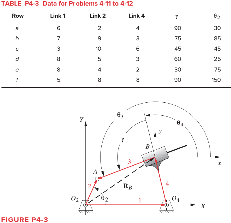
The link lengths and the value of

Trending nowThis is a popular solution!

Chapter 4 Solutions
DESIGN OF MACHINERY
Additional Engineering Textbook Solutions
HEAT+MASS TRANSFER:FUND.+APPL.
Fundamentals of Heat and Mass Transfer
Thinking Like an Engineer: An Active Learning Approach (3rd Edition)
Vector Mechanics for Engineers: Statics and Dynamics
Machine Tool Practices (10th Edition)
Thinking Like an Engineer: An Active Learning Approach (4th Edition)


- Given: AB = 0.1 m , CB = 0.4 m, CD = 0.6 m, AD = 0.8 m For the linkage shown below, CD moves back and forth spinning flywheel AB, link CD is the input link. a.) Find the maximum angle in degrees, that is the angle between the extreme positions by the link CD when the circle AB rotates 360 degrees? b.) Why is the wheel able to rotate fully and not get locked up when CD and AB are inline (collinear)? Where's a real life example where this mechanism may be used?arrow_forwardWhat is the equivalent root of the system of the figure using the displacement of the block as a generalized coordinatearrow_forwardBlock 4 slides in the slot in the fixed piece 1. Axis Q2 of crank 2 is fixed on 1. Q2A = 1.5 inches, and AB = 4.5 inches. Draw the mechanism, assuming dimensions for 1, if desired or use center lines only. Draw the four-bar linkage for this mechanism, properly rotate the linkage Q2ABQ4∞, name each link, and show the finite infinite cranks.arrow_forward
- Please Solve Q4 with sketch T-S diagramarrow_forwardPls help me with my plates Block 4 slides in the slot in the fixed piece 1. Axis Q2 of crank 2 is fixed on 1. Q2A = 1.5 inches, and AB = 4.5 inches. Draw the mechanism, assuming dimensions for 1, if desired or use center lines only. Draw the four-bar linkage for this mechanism, properly rotate the linkage Q2ABQ4∞, name each link, and show the finite infinite cranks.arrow_forwardcan you help me to do the position analysis of this mechanism and find the mathemetical expressions to calculate each angle ggiven thank you.arrow_forward
- The general linkage configuration and terminology for an offset fourbar slider-crank linkage are shown in Figure below. The link lengths and the values of 02 and w2 are defined in. For the row(s) b and c, find the velocities of the pin joints A and B and the velocity of slip at the sliding joint using an analytical method. Draw the linkage to scale and label it before setting up the equations. y A 03 B Y 4 Link 3 A W2 Offset 02 04 = 90° Link 2 X 02 Slider position d TABLE P6-2 Data for Problems 6-6 to 6-7† Row Link 2 Link 3 Offset 02 02 a 1.4 4 1 45 10 2 -3 60 -12 3 8 2 -30 -15arrow_forwardFind the velocity and acceleration of point B for the linkage shown in the figure if VA= 1 ft/s. (Using Complex Algebraic approach do the Position Analysis; Velocity Analysis and Acceleration Analysis then solve the problem please)arrow_forwardRj.gandhi Crank 2 of the pushlink mechanism shown in the figure is driven at a constant angular velocity ω2 = 60 rad/s (CW). Find the velocity and acceleration of point D and the angular velocity and acceleration of links 3 and 4. Using the Velocity and Acceleration graphical analysis polygons.arrow_forward
- The kinematic scheme of the mechanism is given. Point C is the center of curvature of the link 3 at the point of the contact. Link 2 is with circular shape with center point B. Find the degrees of freedom.arrow_forwardIn the kinematic diagram, the limb dimensions are given below, in the arm slide mechanism, the actuating limb angular position is (theta)θ12 = 600 and the speed of the mechanism is given as (thetadot)θ'12 = 50 rad / s . Do the following operations respectively. Write the Vector Closure Equation into scalar form.arrow_forwardGiven the vectors in Figure P1-2, use a scale of 1 inch = 10 units, and determine the following vectors: Figure P1-2 B=10 ; 270⁰ C=15 ; 210⁰ D=12,5 ; 315⁰ E= 7,5 ; 75⁰ F = 10 ; 215⁰ G= 15 ; 100⁰arrow_forward
 Elements Of ElectromagneticsMechanical EngineeringISBN:9780190698614Author:Sadiku, Matthew N. O.Publisher:Oxford University Press
 Mechanics of Materials (10th Edition)Mechanical EngineeringISBN:9780134319650Author:Russell C. HibbelerPublisher:PEARSON
 Thermodynamics: An Engineering ApproachMechanical EngineeringISBN:9781259822674Author:Yunus A. Cengel Dr., Michael A. BolesPublisher:McGraw-Hill Education
 Control Systems EngineeringMechanical EngineeringISBN:9781118170519Author:Norman S. NisePublisher:WILEY
 Mechanics of Materials (MindTap Course List)Mechanical EngineeringISBN:9781337093347Author:Barry J. Goodno, James M. GerePublisher:Cengage Learning
 Engineering Mechanics: StaticsMechanical EngineeringISBN:9781118807330Author:James L. Meriam, L. G. Kraige, J. N. BoltonPublisher:WILEY