
DESIGN OF MACHINERY
6th Edition
ISBN: 9781260113310
Author: Norton
Publisher: RENT MCG
expand_more
expand_more
format_list_bulleted
Concept explainers
Videos
Textbook Question
Chapter 4, Problem 4.18P
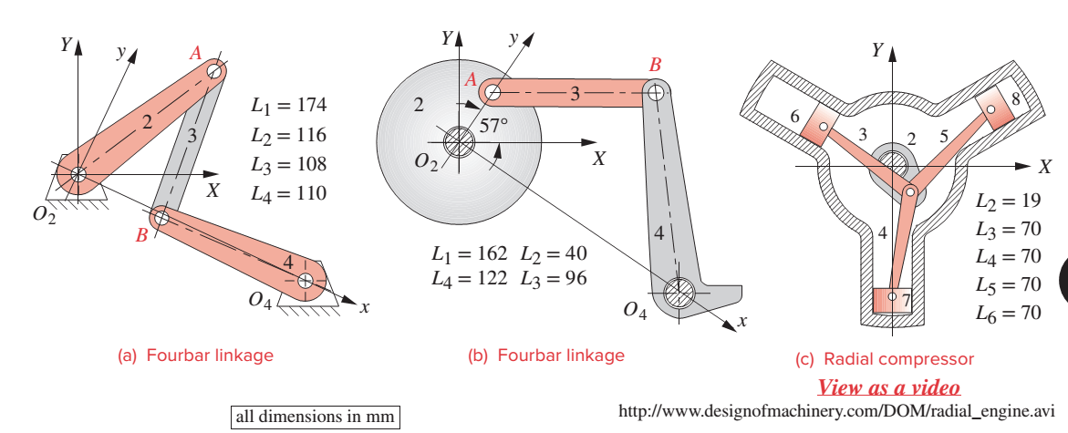
Figure P4-5 shows the
- The angle between the X and x axes is 25°. Find the angular displacement of link 4 when link 2 rotates clockwise from the position shown (+370) to horizontal (0°). How does the transmission angle vary and what is its minimum between those two positions? Find the toggle positions of this linkage in terms of the angle of link 2.
- Find and plot the angular position of links 3 and 4 and the transmission angle as a function of the angle of link 2 as it rotates through one revolution.
- Find and plot the position of any one piston as a function of the angle of crank 2 as it rotates through one revolution. Once one piston’s motion is defined, find the
Expert Solution & Answer

Trending nowThis is a popular solution!

Students have asked these similar questions
Displacement Diagrams—Analytical
For the compressor mechanism shown in FigureP3.5, analytically create a displacement diagram for the position of the piston as the crank rotates a full
revolution counterclockwise.
Draw the kinematic diagram of the following mechanism
Problem 2 The linkage in Figure P7-5b has o4A = o2A = 0.75, AB = 1.5, and AC = 1.2 in. The effective crank angle in the position shown is 77° and angle BAC = 30°. Find a3, AA, AB, Ac for the position shown for w2 = 15 rad/sec and a2 = 10 rad/sec^2 in the directions shown using an analytic method. (Hint: Create an effective linkage for the position shown and analyze it as a pin-jointed fourbar.)
the linkage has a parallelogram form Assume rolling contact
Chapter 4 Solutions
DESIGN OF MACHINERY
Ch. 4 - A position vector is defined as having a length...Ch. 4 - A particle is traveling along an arc of 6.5-in...Ch. 4 - Repeat problem 4-2 considering points A and B to...Ch. 4 - Repeat Problem 4-2 with the particles path defined...Ch. 4 - Repeat Problem 4-3 with the path of the particle...Ch. 4 - The link lengths and the value of 2 for some...Ch. 4 - Repeat Problem 4-6 except solve by the vector loop...Ch. 4 - Expand equation 4.7b and prove that it reduces to...Ch. 4 - The link lengths and the value of 2 and offset for...Ch. 4 - Repeat Problem 4-9 except solve by the vector loop...
Ch. 4 - The link lengths and the value of 2 and for some...Ch. 4 - Repeat Problem 4-11 except solve by the vector...Ch. 4 - Find the transmission angles of the linkages in...Ch. 4 - Find the minimum and maximum values of the...Ch. 4 - Find the input angles corresponding to the toggle...Ch. 4 - The link lengths. gear ratio (). phase angle (),...Ch. 4 - Repeat Problem 4-16 except solve by the vector...Ch. 4 - Figure P4-5 shows the mechanisms for the following...Ch. 4 - For one revolution of driving link 2 of the...Ch. 4 - Figure P4-7 shows a power hacksaw, used to cut...Ch. 4 - For the linkage in Figure P4-8, find its limit...Ch. 4 - For the walking-beam mechanism of Figure P4-9,...Ch. 4 - For the linkage in Figure P4-10, calculate and...Ch. 4 - For the linkage in Figure P4-11, calculate and...Ch. 4 - For the linkage in Figure P4-12, find its limit...Ch. 4 - Prob. 4.26PCh. 4 - For the linkage in Figure P4-13, find its limit...Ch. 4 - Prob. 4.28PCh. 4 - For the linkage in Figure P4-15, find its limit...Ch. 4 - For the linkage in Figure P4-15, find its limit...Ch. 4 - Prob. 4.31PCh. 4 - Prob. 4.32PCh. 4 - Figure 4-22 plots the cubic function from equation...Ch. 4 - Write a computer program or use an equation solver...Ch. 4 - Prob. 4.35PCh. 4 - Prob. 4.36PCh. 4 - Write a computer program or use an equation solver...Ch. 4 - Write a computer program or use an equation solver...Ch. 4 - Prob. 4.39PCh. 4 - Prob. 4.40PCh. 4 - Write a computer program or use an equation solver...Ch. 4 - Prob. 4.42PCh. 4 - Prob. 4.43PCh. 4 - Prob. 4.44PCh. 4 - Model the linkage shown in Figure 3-37a in...Ch. 4 - Prob. 4.46PCh. 4 - Prob. 4.47PCh. 4 - Prob. 4.48PCh. 4 - Prob. 4.49PCh. 4 - Prob. 4.50PCh. 4 - Figure 3-29g shows Evans approximate straight-line...Ch. 4 - For the linkage in Figure P4-16, what are the...Ch. 4 - The coordinates of the point P1 on link 4 in...Ch. 4 - Write a computer program or use an equation solver...Ch. 4 - For the linkage in Figure P4-17, calculate the...Ch. 4 - Prob. 4.56PCh. 4 - Prob. 4.57PCh. 4 - The elliptical trammel in Figure P4-18 must be...Ch. 4 - Prob. 4.59PCh. 4 - Prob. 4.60PCh. 4 - Repeat Problem 4-60 except solve by the vector...Ch. 4 - Write a computer program or use an equation solver...Ch. 4 - Write a computer program or use an equation solver...Ch. 4 - Write a computer program or use an equation solver...Ch. 4 - Write a computer program or use an equation solver...Ch. 4 - Figure P4-20 shows a cut-away view of a mechanism...Ch. 4 - For the linkage in Figure 3-32a, calculate and...
Knowledge Booster


Learn more about
Need a deep-dive on the concept behind this application? Look no further. Learn more about this topic, mechanical-engineering and related others by exploring similar questions and additional content below.Similar questions
- The link lengths, value of theta2, and offset for some fourbar slider-crank linkages are defined inTable P4-2. The linkage configuration and terminology are shown in Figure P4-2. For row a,draw the linkage to scale and graphically find all possible solutions (both open and crossed)for angles theta3 and slider position d.arrow_forwardDraw the kinematic digrams of the following mechanisms and compute the number of Degreesof Freedom (Mobility) of the figure belowarrow_forwardRefer to the figure below for the mechanism.If link 2 rotates at a speed of 60 revolutions per minute, find the velocity, using resolution and composition method of: A point connecting link 2 to link 3 A point at the center of link 2 A point at the center of link 3 Of the slider Also, locate all the instantaneous centers. Use counterclockwise direction.arrow_forward
- The kinematic scheme of the mechanism is given. Point C is the center of curvature of the link 3 at the point of the contact. Link 2 is with circular shape with center point B. Find the degrees of freedom.arrow_forwardThe linkage in Figure P7-5b has 04A = O2A = 0.75 , AB = 1.5 , and AC = 1.2 in . The effective crank angle in the position shown is 77º and angle BAC = 30 ° . Find a3 , AA , AB , Ac for the position shown for m2 = 15 rad / sec and a2 = 10 rad / sec2 in the directions shown using an analytical method . ( Hint : Create an effective linkage for the position shown and analyze it as a pin - jointed fourbar . ) the linkage has a parallelogram form Assume rolling contact C 02 A 3 . B 02 02 Tarrow_forwardRefer to the figure below for the mechanism. If link 2 rotates at a speed of 60 revolutions per minute in a counterclockwise direction , find the velocity, using resolution and composition method of: A point connecting link 2 to link 3 A point at the center of link 2 A point at the center of link 3 Of the slider Also, locate all the instantaneous centers.arrow_forward
- Find the kinematic chain and degrees of freedom of the mechanism in the figure. PLEASE HELParrow_forwardThe linkage Q₂BCDEQ₄KF represents the mechanism of the Corliss non-releasing valve gear. Q₂B is a crank 3⅛- inches long oscillating to the right of fixed center Q₂. Q₂C is another crank which is 3⅜-inches long and oscillates below Q₂. Q₄ is a fixed center on a horizontal line through Q₂ and 6 -inches to right of Q₂. EQ₄K to right of Q₄E. Q₄E = 3⅝- inches and Q₄K = 5 -inches. CE is a connecting rod 3½-inches long. BD is a link 2 - inches long connecting B to link CE at D, 1 -inch. from C. KF is a connecting link 8- inches long extending to right of K and is attached to a slide block at F which moves on a horizontal line parallel to and 3-inches below Q₂Q₄. When F, moving to left, reaches a position such that K is to the left of Q₄, and Q₄K makes an angle of 15º to left of vertical, it has a velocity of 5 fps. 1.1 Draw and label the mechanism of the Corliss non-releasing valve gear. 1.2 Find the velocity K in feet per second 1.3 Find the velocity of E in feet per second 1.4 Find the…arrow_forwardDraw the kinematic diagrams of the following mechanisms and compute the number of Degreesof Freedom (Mobility)arrow_forward
- P4.5 For the mechanism shown in figure P4.5, determine (a) the angular velocity of link 3 (b) the velocity of point A2 with respect to point A3 (c) the Coriolis acceleration of point A2 with respect to point A3 use a complex numbers approach ro2A=5.0cm, angle2=135 degrees, dotangle2=80 rpm CW.arrow_forwardPlease Solve Q4 with sketch T-S diagramarrow_forwardP4.8 Determine the rotational speed of link 3 of the mechanism given in figure P4.8 for the position shown. Use a complex numbers approacharrow_forward
arrow_back_ios
SEE MORE QUESTIONS
arrow_forward_ios
Recommended textbooks for you
 Elements Of ElectromagneticsMechanical EngineeringISBN:9780190698614Author:Sadiku, Matthew N. O.Publisher:Oxford University Press
 Mechanics of Materials (10th Edition)Mechanical EngineeringISBN:9780134319650Author:Russell C. HibbelerPublisher:PEARSON
 Thermodynamics: An Engineering ApproachMechanical EngineeringISBN:9781259822674Author:Yunus A. Cengel Dr., Michael A. BolesPublisher:McGraw-Hill Education
 Control Systems EngineeringMechanical EngineeringISBN:9781118170519Author:Norman S. NisePublisher:WILEY
 Mechanics of Materials (MindTap Course List)Mechanical EngineeringISBN:9781337093347Author:Barry J. Goodno, James M. GerePublisher:Cengage Learning
 Engineering Mechanics: StaticsMechanical EngineeringISBN:9781118807330Author:James L. Meriam, L. G. Kraige, J. N. BoltonPublisher:WILEY
Elements Of Electromagnetics
Mechanical Engineering
ISBN:9780190698614
Author:Sadiku, Matthew N. O.
Publisher:Oxford University Press
Mechanics of Materials (10th Edition)
Mechanical Engineering
ISBN:9780134319650
Author:Russell C. Hibbeler
Publisher:PEARSON
Thermodynamics: An Engineering Approach
Mechanical Engineering
ISBN:9781259822674
Author:Yunus A. Cengel Dr., Michael A. Boles
Publisher:McGraw-Hill Education
Control Systems Engineering
Mechanical Engineering
ISBN:9781118170519
Author:Norman S. Nise
Publisher:WILEY
Mechanics of Materials (MindTap Course List)
Mechanical Engineering
ISBN:9781337093347
Author:Barry J. Goodno, James M. Gere
Publisher:Cengage Learning
Engineering Mechanics: Statics
Mechanical Engineering
ISBN:9781118807330
Author:James L. Meriam, L. G. Kraige, J. N. Bolton
Publisher:WILEY
Power Transmission; Author: Terry Brown Mechanical Engineering;https://www.youtube.com/watch?v=YVm4LNVp1vA;License: Standard Youtube License