
DESIGN OF MACHINERY
6th Edition
ISBN: 9781260113310
Author: Norton
Publisher: RENT MCG
expand_more
expand_more
format_list_bulleted
Videos
Textbook Question
Chapter 4, Problem 4.20P
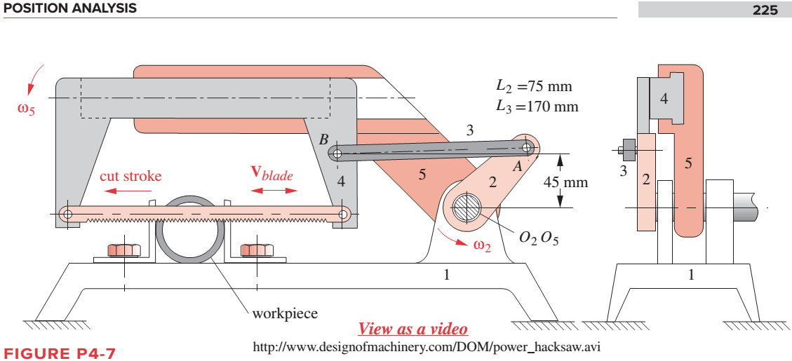
Figure P4-7 shows a power hacksaw, used to cut metal. Link 5 pivots at
Expert Solution & Answer
Want to see the full answer?
Check out a sample textbook solution
Students have asked these similar questions
Displacement Diagrams—Analytical
For the compressor mechanism shown in FigureP3.5, analytically create a displacement diagram for the position of the piston as the crank rotates a full
revolution counterclockwise.
Refer to the figure below for the mechanism. If link 2 rotates at a speed of 60 revolutions per minute in a counterclockwise direction , find the velocity, using resolution and composition method of:
A point connecting link 2 to link 3
A point at the center of link 2
A point at the center of link 3
Of the slider
Also, locate all the instantaneous centers.
Refer to the figure below for the mechanism.If link 2 rotates at a speed of 60 revolutions per minute, find the velocity, using resolution and composition method of:
A point connecting link 2 to link 3
A point at the center of link 2
A point at the center of link 3
Of the slider
Also, locate all the instantaneous centers. Use counterclockwise direction.
Chapter 4 Solutions
DESIGN OF MACHINERY
Ch. 4 - A position vector is defined as having a length...Ch. 4 - A particle is traveling along an arc of 6.5-in...Ch. 4 - Repeat problem 4-2 considering points A and B to...Ch. 4 - Repeat Problem 4-2 with the particles path defined...Ch. 4 - Repeat Problem 4-3 with the path of the particle...Ch. 4 - The link lengths and the value of 2 for some...Ch. 4 - Repeat Problem 4-6 except solve by the vector loop...Ch. 4 - Expand equation 4.7b and prove that it reduces to...Ch. 4 - The link lengths and the value of 2 and offset for...Ch. 4 - Repeat Problem 4-9 except solve by the vector loop...
Ch. 4 - The link lengths and the value of 2 and for some...Ch. 4 - Repeat Problem 4-11 except solve by the vector...Ch. 4 - Find the transmission angles of the linkages in...Ch. 4 - Find the minimum and maximum values of the...Ch. 4 - Find the input angles corresponding to the toggle...Ch. 4 - The link lengths. gear ratio (). phase angle (),...Ch. 4 - Repeat Problem 4-16 except solve by the vector...Ch. 4 - Figure P4-5 shows the mechanisms for the following...Ch. 4 - For one revolution of driving link 2 of the...Ch. 4 - Figure P4-7 shows a power hacksaw, used to cut...Ch. 4 - For the linkage in Figure P4-8, find its limit...Ch. 4 - For the walking-beam mechanism of Figure P4-9,...Ch. 4 - For the linkage in Figure P4-10, calculate and...Ch. 4 - For the linkage in Figure P4-11, calculate and...Ch. 4 - For the linkage in Figure P4-12, find its limit...Ch. 4 - Prob. 4.26PCh. 4 - For the linkage in Figure P4-13, find its limit...Ch. 4 - Prob. 4.28PCh. 4 - For the linkage in Figure P4-15, find its limit...Ch. 4 - For the linkage in Figure P4-15, find its limit...Ch. 4 - Prob. 4.31PCh. 4 - Prob. 4.32PCh. 4 - Figure 4-22 plots the cubic function from equation...Ch. 4 - Write a computer program or use an equation solver...Ch. 4 - Prob. 4.35PCh. 4 - Prob. 4.36PCh. 4 - Write a computer program or use an equation solver...Ch. 4 - Write a computer program or use an equation solver...Ch. 4 - Prob. 4.39PCh. 4 - Prob. 4.40PCh. 4 - Write a computer program or use an equation solver...Ch. 4 - Prob. 4.42PCh. 4 - Prob. 4.43PCh. 4 - Prob. 4.44PCh. 4 - Model the linkage shown in Figure 3-37a in...Ch. 4 - Prob. 4.46PCh. 4 - Prob. 4.47PCh. 4 - Prob. 4.48PCh. 4 - Prob. 4.49PCh. 4 - Prob. 4.50PCh. 4 - Figure 3-29g shows Evans approximate straight-line...Ch. 4 - For the linkage in Figure P4-16, what are the...Ch. 4 - The coordinates of the point P1 on link 4 in...Ch. 4 - Write a computer program or use an equation solver...Ch. 4 - For the linkage in Figure P4-17, calculate the...Ch. 4 - Prob. 4.56PCh. 4 - Prob. 4.57PCh. 4 - The elliptical trammel in Figure P4-18 must be...Ch. 4 - Prob. 4.59PCh. 4 - Prob. 4.60PCh. 4 - Repeat Problem 4-60 except solve by the vector...Ch. 4 - Write a computer program or use an equation solver...Ch. 4 - Write a computer program or use an equation solver...Ch. 4 - Write a computer program or use an equation solver...Ch. 4 - Write a computer program or use an equation solver...Ch. 4 - Figure P4-20 shows a cut-away view of a mechanism...Ch. 4 - For the linkage in Figure 3-32a, calculate and...
Knowledge Booster


Learn more about
Need a deep-dive on the concept behind this application? Look no further. Learn more about this topic, mechanical-engineering and related others by exploring similar questions and additional content below.Similar questions
- Analytically position the links for the shearing mech anism in the configuration shown in Figure P4.7. Then reposition the links as the 0.75-in. crank is rotated 100 deg clockwise. Determine the resulting dis placement of the blade.arrow_forwardFor the walking-beam mechanism of Figure P4-9, calculate and plot the xand y components of the position of the coupler point P for one complete revolution of the crank O2A. Hint: Calculate them first with respect to the ground link O204 and then transform them into the global XY coordinate system (i.e., horizontal and vertical in the figure). Scale the figure for any additional information neededarrow_forwardThe linkage Q₂BCDEQ₄KF represents the mechanism of the Corliss non-releasing valve gear. Q₂B is a crank 3⅛- inches long oscillating to the right of fixed center Q₂. Q₂C is another crank which is 3⅜-inches long and oscillates below Q₂. Q₄ is a fixed center on a horizontal line through Q₂ and 6 -inches to right of Q₂. EQ₄K to right of Q₄E. Q₄E = 3⅝- inches and Q₄K = 5 -inches. CE is a connecting rod 3½-inches long. BD is a link 2 - inches long connecting B to link CE at D, 1 -inch. from C. KF is a connecting link 8- inches long extending to right of K and is attached to a slide block at F which moves on a horizontal line parallel to and 3-inches below Q₂Q₄. When F, moving to left, reaches a position such that K is to the left of Q₄, and Q₄K makes an angle of 15º to left of vertical, it has a velocity of 5 fps. 1.1 Draw and label the mechanism of the Corliss non-releasing valve gear. 1.2 Find the velocity K in feet per second 1.3 Find the velocity of E in feet per second 1.4 Find the…arrow_forward
- Draw the kinematic digrams of the following mechanisms and compute the number of Degreesof Freedom (Mobility) of the figure belowarrow_forwardPlease Solve Q4 with sketch T-S diagramarrow_forwardThe angular velocity of the member A of the mechanism in Figure P8-196 is 2.0 rad/s clockwise. Calculate the velocities cities of points P and Q.arrow_forward
- Block 4 slides in the slot in the fixed piece 1. Axis Q2 of crank 2 is fixed on 1. Q2A = 1.5 inches, and AB = 4.5 inches. Draw the mechanism, assuming dimensions for 1, if desired or use center lines only. Draw the four-bar linkage for this mechanism, properly rotate the linkage Q2ABQ4∞, name each link, and show the finite infinite cranks.arrow_forwardPls help me with my plates Block 4 slides in the slot in the fixed piece 1. Axis Q2 of crank 2 is fixed on 1. Q2A = 1.5 inches, and AB = 4.5 inches. Draw the mechanism, assuming dimensions for 1, if desired or use center lines only. Draw the four-bar linkage for this mechanism, properly rotate the linkage Q2ABQ4∞, name each link, and show the finite infinite cranks.arrow_forwardP4.8 Determine the rotational speed of link 3 of the mechanism given in figure P4.8 for the position shown. Use a complex numbers approacharrow_forward
- Given: AB = 0.1 m , CB = 0.4 m, CD = 0.6 m, AD = 0.8 m For the linkage shown below, CD moves back and forth spinning flywheel AB, link CD is the input link. a.) Find the maximum angle in degrees, that is the angle between the extreme positions by the link CD when the circle AB rotates 360 degrees? b.) Why is the wheel able to rotate fully and not get locked up when CD and AB are inline (collinear)? Where's a real life example where this mechanism may be used?arrow_forwardIn the Four-bar linkage shown in the figure below Va= 60in/sec. A and B are points in the same link. (A) Find the velocity if B. (B) Find the angular velocity of link 3arrow_forwardDraw the kinematic diagram of the following mechanismarrow_forward
arrow_back_ios
SEE MORE QUESTIONS
arrow_forward_ios
Recommended textbooks for you
 Elements Of ElectromagneticsMechanical EngineeringISBN:9780190698614Author:Sadiku, Matthew N. O.Publisher:Oxford University Press
 Mechanics of Materials (10th Edition)Mechanical EngineeringISBN:9780134319650Author:Russell C. HibbelerPublisher:PEARSON
 Thermodynamics: An Engineering ApproachMechanical EngineeringISBN:9781259822674Author:Yunus A. Cengel Dr., Michael A. BolesPublisher:McGraw-Hill Education
 Control Systems EngineeringMechanical EngineeringISBN:9781118170519Author:Norman S. NisePublisher:WILEY
 Mechanics of Materials (MindTap Course List)Mechanical EngineeringISBN:9781337093347Author:Barry J. Goodno, James M. GerePublisher:Cengage Learning
 Engineering Mechanics: StaticsMechanical EngineeringISBN:9781118807330Author:James L. Meriam, L. G. Kraige, J. N. BoltonPublisher:WILEY
Elements Of Electromagnetics
Mechanical Engineering
ISBN:9780190698614
Author:Sadiku, Matthew N. O.
Publisher:Oxford University Press
Mechanics of Materials (10th Edition)
Mechanical Engineering
ISBN:9780134319650
Author:Russell C. Hibbeler
Publisher:PEARSON
Thermodynamics: An Engineering Approach
Mechanical Engineering
ISBN:9781259822674
Author:Yunus A. Cengel Dr., Michael A. Boles
Publisher:McGraw-Hill Education
Control Systems Engineering
Mechanical Engineering
ISBN:9781118170519
Author:Norman S. Nise
Publisher:WILEY
Mechanics of Materials (MindTap Course List)
Mechanical Engineering
ISBN:9781337093347
Author:Barry J. Goodno, James M. Gere
Publisher:Cengage Learning
Engineering Mechanics: Statics
Mechanical Engineering
ISBN:9781118807330
Author:James L. Meriam, L. G. Kraige, J. N. Bolton
Publisher:WILEY
Polymer Basics; Author: Tonya Coffey;https://www.youtube.com/watch?v=c5gFHpWvDXk;License: Standard youtube license