
Concept explainers
Videos
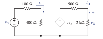
Find the voltage gain
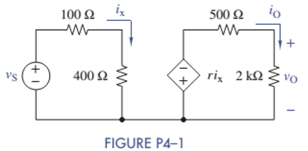
Voltage gain
Answer to Problem 4.1P
The values are
Explanation of Solution
Given:
Calculation:
Apply KVL to the first loop,
Apply KVL to the second loop,
But
Divide equation (2) by equation (1).
Want to see more full solutions like this?
Chapter 4 Solutions
ANALYSIS+DESIGN OF LINEAR CIRCUITS(LL)
Additional Engineering Textbook Solutions
Electric Circuits (10th Edition)
Basic Engineering Circuit Analysis
Fundamentals of Applied Electromagnetics (7th Edition)
Introductory Circuit Analysis (13th Edition)
Electrical Engineering: Principles & Applications (7th Edition)
Electric Circuits. (11th Edition)


- Q4.Explain in detail in your own words, how do you eliminate the loss of string power due to shadow with figure. ( students has to write the related figures neatly)arrow_forwardUse the idea presented in Figure 4 to design a weighted summer that provides; vO= 2v1 + v2 − 4v3 (That is, you have to propose resistance value for each resistor to get the desired output)arrow_forwardThere are three input voltages: vI1=2 + 2 sin(wt) V, vI2= 0.5 sin(wt) V and vI3= -4 V. Usingan inverting summing amplifier, design a circuit that has an output vo= -6 sin (wt) V. Bydesign specification the maximum current in any resistor is limited to 120 μA.arrow_forward
- Find the required resistance R4 to obtain the gain V0/Vi = -5 in amplifier circuit.arrow_forwardWhat are the voltages VO and VID in the op amp circuit shown for dc input voltages of (a) VI = 300 mV and (b) VI = 600 mV if the 1-kΩ resistor is replaced by a 910-Ω resistor.arrow_forwardPlease answer fast Below is an Inverting Op-Amp circuit with 3 1k resistors. V_ = 5V and Vout = -15V. Please show all steps for calculating Vout and list the total resistance of this circuit. I keep getting 10V for Vout so I'm not sure where I'm going wrong.arrow_forward
- Draw a circuit that contains a 5–Ω resistor, a 10-V voltage source, and a currentcontrolled voltage source having a gain constant of 2 Ω. Assume that the current through the resistor is the control current for the controlled source. Place all three elements in series.arrow_forwardIn the circuit in Figure 4, find the value of Vc (t) for t>0 ?arrow_forward(a) Design a half-subtractor circuit with inputs x and y and outputs Diff and B out . The circuit subtracts the bits x − y and places the difference in D and the borrow in B out .(b) Design a full-subtractor circuit with three inputs x, y, B in and two outputs Diff and B out . The circuit subtracts x − y − B in , where B in is the input borrow, B out is the output borrow, and Diff is the difference.arrow_forward
- HELP I NEED THIS QUICKLY a:Write the equation Vo according to the block diagram given below. b: Design the circuit that will perform the operation by using 0.5 V and 10 V direct current (DC) sources with a single OPAMP.arrow_forwardWhat is the voltage gain of the circuit? (V out / V in =?)arrow_forwardFor the circuit belowa. What is the current flow through R8 and the voltage across R4b. Total power dissipated by R7 and the total power dissipated on circuit.arrow_forward
 Introductory Circuit Analysis (13th Edition)Electrical EngineeringISBN:9780133923605Author:Robert L. BoylestadPublisher:PEARSON
 Delmar's Standard Textbook Of ElectricityElectrical EngineeringISBN:9781337900348Author:Stephen L. HermanPublisher:Cengage Learning
 Programmable Logic ControllersElectrical EngineeringISBN:9780073373843Author:Frank D. PetruzellaPublisher:McGraw-Hill Education
 Fundamentals of Electric CircuitsElectrical EngineeringISBN:9780078028229Author:Charles K Alexander, Matthew SadikuPublisher:McGraw-Hill Education
 Electric Circuits. (11th Edition)Electrical EngineeringISBN:9780134746968Author:James W. Nilsson, Susan RiedelPublisher:PEARSON
 Engineering ElectromagneticsElectrical EngineeringISBN:9780078028151Author:Hayt, William H. (william Hart), Jr, BUCK, John A.Publisher:Mcgraw-hill Education,