
Concept explainers
Videos
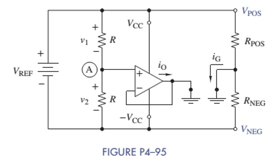
Bipolar Power Supply Voltages
The circuit in Figure P4-95 produces bipolar power supply voltages
- Show that
- If
- In effect, the OP AMP creates a "virtual ground" at point
Want to see the full answer?
Check out a sample textbook solution
Chapter 4 Solutions
ANALYSIS+DESIGN OF LINEAR CIRCUITS(LL)


- What are the voltages VO and VID in the op amp circuit shown for dc input voltages of (a) VI = 300 mV and (b) VI = 600 mV if the 1-kΩ resistor is replaced by a 910-Ω resistor.arrow_forwardneed help on Q4 ,thanksarrow_forward4- Find the number of times the following loop is performed in 8051 microcontroller ORG 0H MOV R6, #200 BACK: MOV R5, #100 HERE: DJNZ R5, HERE DJNZ R6, BACK ENDarrow_forward
- Figure P4-4 circuit, it is known that v1(0-) = 12V, v2(0-) = 8V, if the switch is closed at t = 0 find v1(0+), v2(0+), i(0-) and i(0 +).arrow_forwardHELP a:Write the equation Vo according to the block diagram given below. b: Design the circuit that will perform the operation by using 0.5 V and 10 V direct current (DC) sources with a single OPAMP.arrow_forwardFind the current i for the circuit of the Figure. Hint: A short circuit can be treated as a 0-V voltage source. The value of current i in Amp isarrow_forward
- Find the required resistance R4 to obtain the gain V0/Vi = -5 in amplifier circuit.arrow_forwardThe supply voltage of the op amp in the circuit is 16 V. If RL = 2,500Ω, assign a resistance value to Rf so that the circuit would deliver 75 mW of power to RL.arrow_forwardDetermine the node voltage va for the circuit in the figureCorrect answer: va=4Varrow_forward
- Q4.Explain in detail in your own words, how do you eliminate the loss of string power due to shadow with figure. ( students has to write the related figures neatly)arrow_forwardPlease answer fast Below is an Inverting Op-Amp circuit with 3 1k resistors. V_ = 5V and Vout = -15V. Please show all steps for calculating Vout and list the total resistance of this circuit. I keep getting 10V for Vout so I'm not sure where I'm going wrong.arrow_forwardsubject: Communication Fundamentals Modulation and Demodulation (give solve sub-parts iv and v)arrow_forward
 Delmar's Standard Textbook Of ElectricityElectrical EngineeringISBN:9781337900348Author:Stephen L. HermanPublisher:Cengage Learning