
Concept explainers
Videos
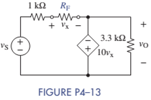
In the circuit of Figure P4-13, the VCVS has of 10,
Want to see the full answer?
Check out a sample textbook solution
Chapter 4 Solutions
ANALYSIS+DESIGN OF LINEAR CIRCUITS(LL)


- Q4.Explain in detail in your own words, how do you eliminate the loss of string power due to shadow with figure. ( students has to write the related figures neatly)arrow_forwardThe circuit shown in Figure P4.4 consists of the cascade connection of three sections. In the total circuit all C’s are equal and all R’s are equal. Let Vo = 0 and find the transfer function T(s) = V2(s)/V1(s).arrow_forwardSolve for V2 given the value of V0 and assuming the opamp is idealarrow_forward
- Figure Q4(b) shows the high input impedance voltage-to-voltage converter. This converter will be used to convert a sensor output of 20 mV to 205 mV into an output voltage of 0 V to 5 V. Determine the value of R1, R2, R3, and R4 (use standard resistor value).arrow_forwardHELP a:Write the equation Vo according to the block diagram given below. b: Design the circuit that will perform the operation by using 0.5 V and 10 V direct current (DC) sources with a single OPAMP.arrow_forwardDesign a circuit to implement the equation z = 4w + (x/4) - 3y The circuit should have one output, corresponding to z, and three inputs, corresponding to w, x, and y. There are multiple ways to design a circuit to create this equation, most will use multiple Op Ampsarrow_forward
- need help on Q4 ,thanksarrow_forwardA computer manufacturing company has approached you to assist it to design a summer circuit for its new type of computers. You are provided with resistors R1, R2, R3, R4 and a feedback resistor Rf. Design and draw the summer circuitii. Derive the formula for the output voltage Vo of the summer circuitarrow_forwardIn the figure, there are 3 R value resistors in the opamp circuit. One of the resistors is variable and is used to express the resistance value that the potentiometer is divided at any moment. Derive the expression that gives the voltage V0.arrow_forward
- What are the voltages VO and VID in the op amp circuit shown for dc input voltages of (a) VI = 300 mV and (b) VI = 600 mV if the output-voltage range of the op amp is limited to the power supply voltages.arrow_forwardUse the idea presented in Figure 4 to design a weighted summer that provides; vO= 2v1 + v2 − 4v3 (That is, you have to propose resistance value for each resistor to get the desired output)arrow_forwardDraw a circuit that contains a 5–Ω resistor, a 10-V voltage source, and a currentcontrolled voltage source having a gain constant of 2 Ω. Assume that the current through the resistor is the control current for the controlled source. Place all three elements in series.arrow_forward
 Introductory Circuit Analysis (13th Edition)Electrical EngineeringISBN:9780133923605Author:Robert L. BoylestadPublisher:PEARSON
 Delmar's Standard Textbook Of ElectricityElectrical EngineeringISBN:9781337900348Author:Stephen L. HermanPublisher:Cengage Learning
 Programmable Logic ControllersElectrical EngineeringISBN:9780073373843Author:Frank D. PetruzellaPublisher:McGraw-Hill Education
 Fundamentals of Electric CircuitsElectrical EngineeringISBN:9780078028229Author:Charles K Alexander, Matthew SadikuPublisher:McGraw-Hill Education
 Electric Circuits. (11th Edition)Electrical EngineeringISBN:9780134746968Author:James W. Nilsson, Susan RiedelPublisher:PEARSON
 Engineering ElectromagneticsElectrical EngineeringISBN:9780078028151Author:Hayt, William H. (william Hart), Jr, BUCK, John A.Publisher:Mcgraw-hill Education,