
Videos
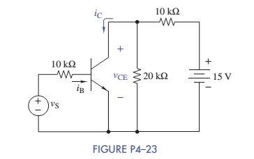
The parameters of the transistor in Figure P4-23 are
Want to see the full answer?
Check out a sample textbook solution
Chapter 4 Solutions
ANALYSIS+DESIGN OF LINEAR CIRCUITS(LL)
Additional Engineering Textbook Solutions
Electric Circuits (10th Edition)
Basic Engineering Circuit Analysis
Fundamentals of Applied Electromagnetics (7th Edition)
Electric Circuits. (11th Edition)
Electrical Engineering: Principles & Applications (7th Edition)
Introductory Circuit Analysis (13th Edition)


- What is the value of r4arrow_forwardUse the idea presented in Figure 4 to design a weighted summer that provides; vO= 2v1 + v2 − 4v3 (That is, you have to propose resistance value for each resistor to get the desired output)arrow_forwardConsider the P-I-N structure shown in Rg. 4-49. The I region is intrinsic. Determine the quantities in (a) and (c). Assume that no bias is applied.arrow_forward
- The input voltage is Vs and the output voltage is Vo. The voltage Vb is adjusted to have the relationship between the input and output. Determine R4 and Vb to have the relationship shown in the graph belowarrow_forwardHELP I NEED THIS QUICKLY a:Write the equation Vo according to the block diagram given below. b: Design the circuit that will perform the operation by using 0.5 V and 10 V direct current (DC) sources with a single OPAMP.arrow_forwardDraw a circuit that contains a 5–Ω resistor, a 10-V voltage source, and a currentcontrolled voltage source having a gain constant of 2 Ω. Assume that the current through the resistor is the control current for the controlled source. Place all three elements in series.arrow_forward
- Find the required resistance R4 to obtain the gain V0/Vi = -5 in amplifier circuit.arrow_forwardWhat are the voltages VO and VID in the op amp circuit shown for dc input voltages of (a) VI = 300 mV and (b) VI = 600 mV if the 1-kΩ resistor is replaced by a 910-Ω resistor.arrow_forwardWhat are the voltages VO and VID in the op amp circuit shown for dc input voltages of (a) VI = 300 mV and (b) VI = 600 mV if the output-voltage range of the op amp is limited to the power supply voltages.arrow_forward
- Design an inverting circuit using a single operational amplifier that will produce the output vo = –4v1 – 6v2.arrow_forwardMAKE A CONNECTION What equation does the tape diagram epresent? Explain how to find the value of 6x using the tape diagram.arrow_forwardPlease answer fast Below is an Inverting Op-Amp circuit with 3 1k resistors. V_ = 5V and Vout = -15V. Please show all steps for calculating Vout and list the total resistance of this circuit. I keep getting 10V for Vout so I'm not sure where I'm going wrong.arrow_forward
 Introductory Circuit Analysis (13th Edition)Electrical EngineeringISBN:9780133923605Author:Robert L. BoylestadPublisher:PEARSON
 Delmar's Standard Textbook Of ElectricityElectrical EngineeringISBN:9781337900348Author:Stephen L. HermanPublisher:Cengage Learning
 Programmable Logic ControllersElectrical EngineeringISBN:9780073373843Author:Frank D. PetruzellaPublisher:McGraw-Hill Education
 Fundamentals of Electric CircuitsElectrical EngineeringISBN:9780078028229Author:Charles K Alexander, Matthew SadikuPublisher:McGraw-Hill Education
 Electric Circuits. (11th Edition)Electrical EngineeringISBN:9780134746968Author:James W. Nilsson, Susan RiedelPublisher:PEARSON
 Engineering ElectromagneticsElectrical EngineeringISBN:9780078028151Author:Hayt, William H. (william Hart), Jr, BUCK, John A.Publisher:Mcgraw-hill Education,