
Suppose we have a capacitance C discharging through a resistance R. Define and give an expression for the time constant. To attain a long time constant, do we need large or small values for R? For C?
The expression for the time constant of the discharging RC circuit and the magnitude of values of R and C for the condition of a large time constant.
Answer to Problem 4.1P
The expression for the time constant for the discharging RC circuit is given as
The value of the values of R and C must be high for a large time constant.
Explanation of Solution
Given information:
Initially, the capacitor is fully charged, the charge on the plates of the capacitor at
The capacitance of the capacitor is C, the resistance of the resistor is R and the time constant of the circuit is
Calculation:
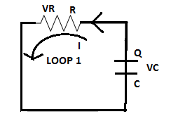
The circuit diagram of the discharging RC circuit is shown below. The capacitor is initially fully charged. Since it is a discharging circuit, the charges on the plate of the capacitor are Q after a time
Applying K.V.L in loop 1
Let the charge on the capacitor at any instant is
Solving the differential equation (2) using the variable separable method,
Where
Hence, the time constant is proportional to the values of resistance and capacitance in the circuit.
To attain a large time constant large value of R is needed as R is directly proportional to the time constant. Also, a large value of C is needed for a large time constant.
Want to see more full solutions like this?
Chapter 4 Solutions
EBK ELECTRICAL ENGINEERING
Additional Engineering Textbook Solutions
Fundamentals of Applied Electromagnetics (7th Edition)
Introductory Circuit Analysis (13th Edition)
Starting out with Visual C# (4th Edition)
Engineering Mechanics: Statics & Dynamics (14th Edition)
Web Development and Design Foundations with HTML5 (8th Edition)
Artificial Intelligence: A Modern Approach

- A variable capacitance and a resistance of 290 ohm are connected in series across a 110-V; 60-Hz supply. Draw the complex or locus of impedance and current as the capacitance changes from 6uF to 32 uF. From the diagram, find the capacitance to give a current of 0.6 A and the current when the capacitance is 11 uF.arrow_forward4. Suppose now that we include a real and ideal battery to create a RC circuit with the resistors in parallel. Imagine that the resistors in parallel go before the capacitor. The battery has an electromotive force E = 4 V. (a) What is kirchoff's law for a charging and discharging capacitor? write out both general expressions and explain what the differences are. Draw plots for both. (b) Over time, the capacitor begins to oscillate in its separation. Solve for the capacitor separation x(t) as a function of time t for a charging unknown сараcitor.arrow_forward91)Give Short Ansaers:- a) Determine the dimensions of and Inductance. 2) Differentiiate classi Fication used c) Difine resoluticn one Capacitance between different for Absolute standards Electrical measurinents accuracys and elror example each,arrow_forward
- Handwrite and step by step solutions.arrow_forwardThe circuit shown in the given figure is a model of a solenoid, such as that used to engage the gear of a car’s starter motor to the engine’s flywheel. The solenoid is constructed by winding a wire around an iron core to make an electromagnet. The resistance R is that of the wire, and the inductance L is due to the electromagnetic effect. When the supply voltage vs is turned on, the resulting current activates the magnet, which moves the starter gear. Obtain the model of the current i given the supply voltage vs.arrow_forwardIt is required to grade a string having seven suspension insulators. If the pin to earth capacitance are all equal to C, determine the line to pin capacitance that would give the same voltage across each insulator (C1, C2, …….C6) of the string.arrow_forward
- I need answer within 5 minutes please please with my best wishesarrow_forward2) C. When the capacitor is fully charged, the top conductor while the bottom conductor D. Electric field lines are and a potential difference is E. The capacitance of a capacitor is defined as F. The unit of capacitance isarrow_forwardState the phase relationship between current and voltage for a resistance, for an inductance, and for a capacitance.arrow_forward
- MLO 2.6 derive phasor form of voltage and current wave from/to the time-domain formarrow_forwardA thyristor switched capacitor consists of: A. A fixed capacitance and a relatively small a relatively small surge limiting inductance B. A fixed capacitance and a relatively large surge limiting inducatance C. A variable capacitance and a relatively small surge limiting inductance D. A Variable capacitance and a relatively large surge limiting inducatncearrow_forwardFor the circuit given in Figure-2, let the switch was initially closed at position-1 for a 5T time and then the switch is moved to position-2 and left there. Determine: i. Draw capacitor charging circuit and time constant for charging circuit. ii. Expression for vc and ic while switch is in position-1. iii. Compute vc and ic at t = 1T time while switch is at position-1. iv. Time constant for discharging circuit and draw discharging circuit. v. Expression for vc and ic while switch is at position-2. vi. Compute vc and ic at t = 1T while switch is at position-2. vii. Sketch the voltage and current plot for charging and discharging of capacitor and indicate voltage and currents points on the plot. 10 kΩ ( 15 kN R1 R3 E R2 5 kN E= 200V Figure-2 C= 20.75miyu Farrow_forward
 Introductory Circuit Analysis (13th Edition)Electrical EngineeringISBN:9780133923605Author:Robert L. BoylestadPublisher:PEARSON
 Delmar's Standard Textbook Of ElectricityElectrical EngineeringISBN:9781337900348Author:Stephen L. HermanPublisher:Cengage Learning
 Programmable Logic ControllersElectrical EngineeringISBN:9780073373843Author:Frank D. PetruzellaPublisher:McGraw-Hill Education
 Fundamentals of Electric CircuitsElectrical EngineeringISBN:9780078028229Author:Charles K Alexander, Matthew SadikuPublisher:McGraw-Hill Education
 Electric Circuits. (11th Edition)Electrical EngineeringISBN:9780134746968Author:James W. Nilsson, Susan RiedelPublisher:PEARSON
 Engineering ElectromagneticsElectrical EngineeringISBN:9780078028151Author:Hayt, William H. (william Hart), Jr, BUCK, John A.Publisher:Mcgraw-hill Education,