
EBK ELECTRICAL ENGINEERING
7th Edition
ISBN: 8220106714201
Author: HAMBLEY
Publisher: YUZU
expand_more
expand_more
format_list_bulleted
Videos
Textbook Question
Chapter 4, Problem 4.5P
At t = 0, a charged 10{
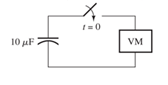
Figure P4.5
Expert Solution & Answer
Want to see the full answer?
Check out a sample textbook solution
Students have asked these similar questions
What do you think will happen to the current if the frequency is adjusted higher in the pure inductance experiment? and what will happen to the current if the frequency is adjusted lower in pure inductance experiment? explain why please
a. As capacitor charges, describe the behavior of:
i.current with time
ii. the voltage across the resistor with time
iii. capacitor voltage withtime
Explain the reason for each behavior.
An electromagnet can be modeled as an inductor in series with a resistor. Consider a large electromagnet of inductance L = 14.5 H and resistance R = 5.50 connected to a 24.0-V battery and switch
as in the figure shown below. After the switch is closed, find the following.
@
(a) the maximum current carried by the electromagnet
4.36
A
(b) the time constant of the circuit
2.63
✔S
(c) the time it takes the current to reach 95.0% of its maximum value.
0.132
x
Your response differs significantly from the correct answer. Rework your solution from the beginning and check each step carefully. st
Chapter 4 Solutions
EBK ELECTRICAL ENGINEERING
Ch. 4 - Suppose we have a capacitance C discharging...Ch. 4 - The dielectric materials used in real capacitors...Ch. 4 - The initial voltage across the capacitor shown in...Ch. 4 - A 100F capacitance is initially charged to 1000 V....Ch. 4 - At t = 0, a charged 10{ F capacitance is connected...Ch. 4 - At time t1 , a capacitance C is charged to a...Ch. 4 - Given an initially charged capacitance that begins...Ch. 4 - The initial voltage across the capacitor shown in...Ch. 4 - In physics, the half-life is often used to...Ch. 4 - We know that a 50F capacitance is charged to an...
Ch. 4 - We know that the capacitor shown in Figure P4.11...Ch. 4 - The purchasing power P of a certain unit of...Ch. 4 - Derive an expression for vC(t) in the circuit of...Ch. 4 - Suppose that at t= 0, we connect an uncharged 10 F...Ch. 4 - Suppose we have a capacitance C that is charged to...Ch. 4 - A person shuffling across a dry carpet can be...Ch. 4 - Prob. 4.17PCh. 4 - Consider the circuit shown in Figure P4.18. Prior...Ch. 4 - List the steps for dc steady-state analysis of RLC...Ch. 4 - Explain why we replace capacitances with open...Ch. 4 - Solve for the steady-state values of i1, i2, and...Ch. 4 - Consider the circuit shown in Figure P4.22. What...Ch. 4 - In the circuit of Figure P4.23, the switch is in...Ch. 4 - The circuit shown in Figure P4.24 has been set up...Ch. 4 - Solve for the steady-state values of i1 , i2, i3,...Ch. 4 - The circuit shown in Figure P4.26 is operating in...Ch. 4 - Prob. 4.27PCh. 4 - Consider the circuit of Figure P4.28 in which the...Ch. 4 - For the circuit shown in Figure P4.29, the switch...Ch. 4 - Consider the circuit of Figure P4.30 in which the...Ch. 4 - Give the expression for the time constant of a...Ch. 4 - A circuit consists of switches that open or close...Ch. 4 - The circuit shown in Figure P4.33 is operating in...Ch. 4 - Consider the circuit shown in Figure P4.34. The...Ch. 4 - Repeat Problem P4.34 given iL(0)=0A .Ch. 4 - Real inductors have series resistance associated...Ch. 4 - Determine expressions for and sketch is(t) to...Ch. 4 - For the circuit shown in Figure P4.38,, find an...Ch. 4 - The circuit shown in Figure P4.39 is operating in...Ch. 4 - Consider the circuit shown in Figure P4.40. A...Ch. 4 - Due to components not shown in the figure, the...Ch. 4 - The switch shown in Figure P4.42 has been closed...Ch. 4 - Determine expressions for and sketch vR(t) to...Ch. 4 - What are the steps in solving a circuit having a...Ch. 4 - Prob. 4.45PCh. 4 - Solve for vC(t) for t > 0 in the circuit of Figure...Ch. 4 - Solve for v(t) for t > 0 in the circuit of Figure...Ch. 4 - Prob. 4.48PCh. 4 - Consider the circuit shown inFigure P4.49. The...Ch. 4 - Consider the circuit shown in Figure P4.50. The...Ch. 4 - The voltage source shown in Figure P4.51 is called...Ch. 4 - Determine the form of the particular solution for...Ch. 4 - Determine the form of the particular solution for...Ch. 4 - Prob. 4.54PCh. 4 - Prob. 4.55PCh. 4 - How can first-or second-order circuits be...Ch. 4 - Prob. 4.57PCh. 4 - Prob. 4.58PCh. 4 - Prob. 4.59PCh. 4 - Sketch a step response for a second-order system...Ch. 4 - A dc source is connected to a series RLC circuit...Ch. 4 - Repeat Problem P4.61 for R = 40 .Ch. 4 - Repeat Problem P4.61 for R = 20 .Ch. 4 - Prob. 4.64PCh. 4 - Repeat Problem P4.64 for R=50 .Ch. 4 - Repeat Problem P4.64 for R=500 .Ch. 4 - Solve for i(t) for t > 0 in the circuit of Figure...Ch. 4 - Prob. 4.68PCh. 4 - Prob. 4.69PCh. 4 - Prob. 4.70PCh. 4 - Use MATLAB to derive an expression for vc(t)in the...Ch. 4 - Prob. 4.72PCh. 4 - Consider the circuit shown in FigureP4.50 in which...Ch. 4 - Prob. 4.74PCh. 4 - Prob. 4.75PCh. 4 - Use MATLAB to solve for the mesh currents in the...Ch. 4 - The switch m the circuit shown in Figure T4.1 is...Ch. 4 - Prob. 4.2PTCh. 4 - Consider the circuit shown in Figure T4.3. Figure...Ch. 4 - Consider the circuit shown in Figure T4.4 in which...Ch. 4 - Write the MATLAB commands to obtain the solution...
Additional Engineering Textbook Solutions
Find more solutions based on key concepts
For the “tank” circuit in Fig. 14.79, find the resonant frequency.
Figure 14.79
For Probs. 14.39, 14.71, and 1...
Fundamentals of Electric Circuits
How many coulombs do 93.8 1016 electrons represent?
Principles Of Electric Circuits
Electric power systems provide energy in a variety of commercial and industrial settings. Make a list of system...
Principles and Applications of Electrical Engineering
Assume a telephone signal travels through a cable at two-thirds the speed of light. How long does it take the s...
Electric Circuits (10th Edition)
With respect to the circuit in Fig. 5.90, (a) employ Thévenin’s theorem to determine the equivalent network see...
Loose Leaf for Engineering Circuit Analysis Format: Loose-leaf
The current source in the circuit shown generates the current pulse
Find (a) v (0); (b) the instant of time gr...
Electric Circuits. (11th Edition)
Knowledge Booster


Learn more about
Need a deep-dive on the concept behind this application? Look no further. Learn more about this topic, electrical-engineering and related others by exploring similar questions and additional content below.Similar questions
- At t=0 a charged 10{μF capacitance is connected to a voltmeter, as shown in Figure P4.5. The meter can be modeled as a resistance. At t=0 the meter reads 50 V. At t=30s, the reading is 25 V. Find the resistance of the voltmeter.arrow_forwardDescribe the behavior of the voltage across the resistor with time as thecapacitor charges. Explain the reason for this behavior.arrow_forwardSuppose we have a very large capacitance (ideally, infinite) charged to 10 V. What othercircuit element has the same current-voltage relationship? Explain your answer.arrow_forward
- 2 The figure is a graph of ... 5 (5 Points) Current Voltage the current across a voltage as a function of the potential difference through it the resistance as a function of the current across a component the current through a component as a function of the voltage across it All three of the above (a), (b), and (c) are true None of the above (a), (b), or (c) is truearrow_forwardWhen subjected to pressure, certain materials create a relatively small voltage. Materials that behave in this manner are called piezoelectrics. Investigate the applications in which piezoelectrics are used. Write a brief report discussing your findings.arrow_forwardQuestion 4. In the circuit below I is a DC current, and v, is a sinusoidal signal. Given the diode has vo=0.75V at io=1.5mA, calculate both the AC and DC voltage across the diode (v.) when I=1mA, R=500, and Assume the capacitors are very large. v₁=100cos(10*n*t). toarrow_forward
- A 20-ohm resistor and a capacitor are connected in series with a battery of 60 volts. At t = 0, there is no charge on the capacitor. Find the capacitance if the current at t = 5 seconds is 3/e^s amperes. Ans. 0.05 Faradsarrow_forwardWhat are the steps in solving a circuit having a resistance, a source, and an inductance (or capacitance)?arrow_forwardA variable capacitance and a resistance of 290 ohm are connected in series across a 110-V; 60-Hz supply. Draw the complex or locus of impedance and current as the capacitance changes from 6uF to 32 uF. From the diagram, find the capacitance to give a current of 0.6 A and the current when the capacitance is 11 uF.arrow_forward
- Linear voltammetry is so called because: The current changes linearly with the potential. temperature changes linearly with time The potential changes linearly with time. The current changes linearly with timearrow_forward4. Suppose now that we include a real and ideal battery to create a RC circuit with the resistors in parallel. Imagine that the resistors in parallel go before the capacitor. The battery has an electromotive force E = 4 V. (a) What is kirchoff's law for a charging and discharging capacitor? write out both general expressions and explain what the differences are. Draw plots for both. (b) Over time, the capacitor begins to oscillate in its separation. Solve for the capacitor separation x(t) as a function of time t for a charging unknown сараcitor.arrow_forward4. WHAT IS MUTUAL INDUCTION AND SELF INDUCTION. WHAT IS THE UNIT OF INDUCTANCE.arrow_forward
arrow_back_ios
SEE MORE QUESTIONS
arrow_forward_ios
Recommended textbooks for you
 Introductory Circuit Analysis (13th Edition)Electrical EngineeringISBN:9780133923605Author:Robert L. BoylestadPublisher:PEARSON
 Delmar's Standard Textbook Of ElectricityElectrical EngineeringISBN:9781337900348Author:Stephen L. HermanPublisher:Cengage Learning
 Programmable Logic ControllersElectrical EngineeringISBN:9780073373843Author:Frank D. PetruzellaPublisher:McGraw-Hill Education
 Fundamentals of Electric CircuitsElectrical EngineeringISBN:9780078028229Author:Charles K Alexander, Matthew SadikuPublisher:McGraw-Hill Education
 Electric Circuits. (11th Edition)Electrical EngineeringISBN:9780134746968Author:James W. Nilsson, Susan RiedelPublisher:PEARSON
 Engineering ElectromagneticsElectrical EngineeringISBN:9780078028151Author:Hayt, William H. (william Hart), Jr, BUCK, John A.Publisher:Mcgraw-hill Education,
Introductory Circuit Analysis (13th Edition)
Electrical Engineering
ISBN:9780133923605
Author:Robert L. Boylestad
Publisher:PEARSON
Delmar's Standard Textbook Of Electricity
Electrical Engineering
ISBN:9781337900348
Author:Stephen L. Herman
Publisher:Cengage Learning
Programmable Logic Controllers
Electrical Engineering
ISBN:9780073373843
Author:Frank D. Petruzella
Publisher:McGraw-Hill Education
Fundamentals of Electric Circuits
Electrical Engineering
ISBN:9780078028229
Author:Charles K Alexander, Matthew Sadiku
Publisher:McGraw-Hill Education
Electric Circuits. (11th Edition)
Electrical Engineering
ISBN:9780134746968
Author:James W. Nilsson, Susan Riedel
Publisher:PEARSON
Engineering Electromagnetics
Electrical Engineering
ISBN:9780078028151
Author:Hayt, William H. (william Hart), Jr, BUCK, John A.
Publisher:Mcgraw-hill Education,
Lead and lag compensation using Bode diagrams; Author: John Rossiter;https://www.youtube.com/watch?v=UBE-Tp173vk;License: Standard Youtube License