
EBK ELECTRICAL ENGINEERING
7th Edition
ISBN: 8220106714201
Author: HAMBLEY
Publisher: YUZU
expand_more
expand_more
format_list_bulleted
Concept explainers
Videos
Textbook Question
Chapter 4, Problem 4.47P
Solve for v(t) for t > 0 in the circuit of Figure P4.47, given that the inductor current is zero prior to t = 0. [Hint: Try a particular solution of the form
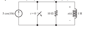
Figure P4.47
Expert Solution & Answer
Want to see the full answer?
Check out a sample textbook solution
Students have asked these similar questions
Consider the circuit shown in Figure P4.50. The initial current in the inductor is i s ( 0+)=0. Write the differential equation for i s(t) and solve. [Hint: Try a particular solution of the form i sp ( t )=A cos( 300t )+B sin( 300t ).]
*P4.34. Consider the circuit shown in Figure P4.34. The initial current in the inductor is i L (0-
)= -0.2 A. Find expressions for i L (t) and v() for t20 and sketch to scale versus time.
R=
2 kl
L=
0.3 A
10 mH
Figure P4.34
P4.34. Consider the circuit shown in Figure P4.34.
The initial current in the inductor is iL (0-)
0. Find expressions for i (t) and v(t) for
t> 0 and sketch to scale versus time.
0.1 A (1)
R =
v(t) 1 k2
t = 0
1 mH
Figure P4.34
Chapter 4 Solutions
EBK ELECTRICAL ENGINEERING
Ch. 4 - Suppose we have a capacitance C discharging...Ch. 4 - The dielectric materials used in real capacitors...Ch. 4 - The initial voltage across the capacitor shown in...Ch. 4 - A 100F capacitance is initially charged to 1000 V....Ch. 4 - At t = 0, a charged 10{ F capacitance is connected...Ch. 4 - At time t1 , a capacitance C is charged to a...Ch. 4 - Given an initially charged capacitance that begins...Ch. 4 - The initial voltage across the capacitor shown in...Ch. 4 - In physics, the half-life is often used to...Ch. 4 - We know that a 50F capacitance is charged to an...
Ch. 4 - We know that the capacitor shown in Figure P4.11...Ch. 4 - The purchasing power P of a certain unit of...Ch. 4 - Derive an expression for vC(t) in the circuit of...Ch. 4 - Suppose that at t= 0, we connect an uncharged 10 F...Ch. 4 - Suppose we have a capacitance C that is charged to...Ch. 4 - A person shuffling across a dry carpet can be...Ch. 4 - Prob. 4.17PCh. 4 - Consider the circuit shown in Figure P4.18. Prior...Ch. 4 - List the steps for dc steady-state analysis of RLC...Ch. 4 - Explain why we replace capacitances with open...Ch. 4 - Solve for the steady-state values of i1, i2, and...Ch. 4 - Consider the circuit shown in Figure P4.22. What...Ch. 4 - In the circuit of Figure P4.23, the switch is in...Ch. 4 - The circuit shown in Figure P4.24 has been set up...Ch. 4 - Solve for the steady-state values of i1 , i2, i3,...Ch. 4 - The circuit shown in Figure P4.26 is operating in...Ch. 4 - Prob. 4.27PCh. 4 - Consider the circuit of Figure P4.28 in which the...Ch. 4 - For the circuit shown in Figure P4.29, the switch...Ch. 4 - Consider the circuit of Figure P4.30 in which the...Ch. 4 - Give the expression for the time constant of a...Ch. 4 - A circuit consists of switches that open or close...Ch. 4 - The circuit shown in Figure P4.33 is operating in...Ch. 4 - Consider the circuit shown in Figure P4.34. The...Ch. 4 - Repeat Problem P4.34 given iL(0)=0A .Ch. 4 - Real inductors have series resistance associated...Ch. 4 - Determine expressions for and sketch is(t) to...Ch. 4 - For the circuit shown in Figure P4.38,, find an...Ch. 4 - The circuit shown in Figure P4.39 is operating in...Ch. 4 - Consider the circuit shown in Figure P4.40. A...Ch. 4 - Due to components not shown in the figure, the...Ch. 4 - The switch shown in Figure P4.42 has been closed...Ch. 4 - Determine expressions for and sketch vR(t) to...Ch. 4 - What are the steps in solving a circuit having a...Ch. 4 - Prob. 4.45PCh. 4 - Solve for vC(t) for t > 0 in the circuit of Figure...Ch. 4 - Solve for v(t) for t > 0 in the circuit of Figure...Ch. 4 - Prob. 4.48PCh. 4 - Consider the circuit shown inFigure P4.49. The...Ch. 4 - Consider the circuit shown in Figure P4.50. The...Ch. 4 - The voltage source shown in Figure P4.51 is called...Ch. 4 - Determine the form of the particular solution for...Ch. 4 - Determine the form of the particular solution for...Ch. 4 - Prob. 4.54PCh. 4 - Prob. 4.55PCh. 4 - How can first-or second-order circuits be...Ch. 4 - Prob. 4.57PCh. 4 - Prob. 4.58PCh. 4 - Prob. 4.59PCh. 4 - Sketch a step response for a second-order system...Ch. 4 - A dc source is connected to a series RLC circuit...Ch. 4 - Repeat Problem P4.61 for R = 40 .Ch. 4 - Repeat Problem P4.61 for R = 20 .Ch. 4 - Prob. 4.64PCh. 4 - Repeat Problem P4.64 for R=50 .Ch. 4 - Repeat Problem P4.64 for R=500 .Ch. 4 - Solve for i(t) for t > 0 in the circuit of Figure...Ch. 4 - Prob. 4.68PCh. 4 - Prob. 4.69PCh. 4 - Prob. 4.70PCh. 4 - Use MATLAB to derive an expression for vc(t)in the...Ch. 4 - Prob. 4.72PCh. 4 - Consider the circuit shown in FigureP4.50 in which...Ch. 4 - Prob. 4.74PCh. 4 - Prob. 4.75PCh. 4 - Use MATLAB to solve for the mesh currents in the...Ch. 4 - The switch m the circuit shown in Figure T4.1 is...Ch. 4 - Prob. 4.2PTCh. 4 - Consider the circuit shown in Figure T4.3. Figure...Ch. 4 - Consider the circuit shown in Figure T4.4 in which...Ch. 4 - Write the MATLAB commands to obtain the solution...
Additional Engineering Textbook Solutions
Find more solutions based on key concepts
For the “tank” circuit in Fig. 14.79, find the resonant frequency.
Figure 14.79
For Probs. 14.39, 14.71, and 1...
Fundamentals of Electric Circuits
Does the severity of an electric shock increase ordecrease with eh of the following changes? a. A decrease in t...
Electric Motors and Control Systems
Three point charges of equal magnitude q, that will yield a zero net electric field at the origin.
Engineering Electromagnetics
Write the nodal equations for the network of Fig. 8.137 using the general approach. Find the nodal voltages usi...
Introductory Circuit Analysis (13th Edition)
Design an ideal inverting op-amp circuit such that the voltage gain is Av=25 . The maximum current in any resis...
Microelectronics: Circuit Analysis and Design
How many coulombs do 93.8 1016 electrons represent?
Principles Of Electric Circuits
Knowledge Booster


Learn more about
Need a deep-dive on the concept behind this application? Look no further. Learn more about this topic, electrical-engineering and related others by exploring similar questions and additional content below.Similar questions
- P4.44. What are the steps in solving a circuit having a resistance, a source, and an inductance (or capacitance)? *P4.45.) Write the differential equation for i(t) and find the complete solution for the circuit of Figure P4.45. [Hint: Try a particular solution of the form ip(t) =Ae-!] %3D 10 H 5et i(t) 5Ω Figure P4.45 P14arrow_forwardP4.42. The switch shown in Figure P4.42 has been closed for a long time prior to t=0, then it opens at t=0 and closes again at t=1 s. Find i L (t) for all t. 6H 121 Figure P4.42arrow_forwardIn the circuit shown in Figure P4.a, the switch is closed at t = 0. The capacitor voltage is charged to vc (0) = 12 V prior to t = 0. The voltage source is us(t) = 35 cos (1000t) V. Find the expressions of uc (t) and ic(t), respectively. vs(t) 500 Ω ww t=0 + v (t) - HH i(t) 1.5 µF 300 Ωarrow_forward
- 6 If the current through a 16-uH inductor is zero at t = 0 and the voltage across the inductor (shown in Figure P4.16) is t 20 us ()la 1.2 nV determine the current through the inductor at t = 30 us. ) (nV) 1.2 20 40 t (us) Figure P4.16arrow_forwardP4.45.) Write the differential equation for i(t) and find the complete solution for the circuit of Figure P4.45. [Hint: Try a particular solution of the form ip (t) = Ae- ]with out Lapluce t = 0 10 H i(t) 5e Figure P4.45arrow_forwardSolve for i L ( t ) for t>0 in the circuit of Figure P4.48. You will need to make an educated guess as to the form of the particular solution. [Hint: The particular solution includes terms with the same functional forms as the terms found in the forcing function and its derivatives.]arrow_forward
- The initial capacitor voltage is 4 V. Switch S1 is closed at t = 0. The charge (in micro C) lost by the capacitor form t = 25 microS to t = 100 microS is:1) 6.992) 8.713) 5.554) 10Please show detailed steps and workarrow_forwardThe circuit shown consists of four capacitors, an ideal battery of emf &, a switch 'S' and an inductor of inductance L. The switch Sis kept open for a long time. Find the maximum current through the inductor after the switch 'S' is closed. 2C 4C C S 8 3C =8arrow_forwardConsider the circuit shown in Figure P4.70. a. Write the differential equation for v(t). b. Find the damping coefficient, the natural frequency, and the form of the complementary solution. c. Usually, for a sinusoidal forcing function, we try a particular solution of the form v p ( t)=A cos( 10 4 t )+B sin( 10 4 t ). Why doesn’t that work in this case? d. Find the particular solution. [Hint: Try a particular solution of the form v p ( t)=At cos( 10 4 t )+B t sin( 10 4 t ). ] e. Find the complete solution for v(t).arrow_forward
- P4.30. Consider the circuit of Figure P4.30 in which the switch has been closed for a long time prior to t=0. Determine the values of v C (t) before t=0 and a long time after t=0. Also, determine the time constant after the switch opens and expressions for v C (t). Sketch v C (t) to scale versus time for -4sts16 s. 2 MA 30 V 2 uF I MO Figure P4.30arrow_forward*P4.61. A dc source is connected to a series RLC circuit by a switch that closes at t = 0, as shown in Figure P4.61. The initial conditions are i(0+) = 0 and vc(0+) = 0. Write the dif- ferential equation for vc(t). Solve for vc(t) given that R = 80 2. t = 0 R 2 mH + V = 50 V i(t) vclt) 5 µF i(0) = 0 vc(0) = 0 Figure P4.61arrow_forwardTitle Find the capacitor voltage in the network shown in Figure P4.2 if the switch closes at t = 0. Assume Description Find the capacitor voltage in the network shown in Figure P4.2 if the switch closes at t = 0. Assume zero initial conditions. Also find the time constant, rise time, and settling time for the capacitor voltage. /=0) W 1.802 0.79 F FIGURE P4.2 Plot the step response for Problem 4 using MATLAB. From your plots, find the time constant, rise time, and settling timearrow_forward
arrow_back_ios
SEE MORE QUESTIONS
arrow_forward_ios
Recommended textbooks for you
 Introductory Circuit Analysis (13th Edition)Electrical EngineeringISBN:9780133923605Author:Robert L. BoylestadPublisher:PEARSON
 Delmar's Standard Textbook Of ElectricityElectrical EngineeringISBN:9781337900348Author:Stephen L. HermanPublisher:Cengage Learning
 Programmable Logic ControllersElectrical EngineeringISBN:9780073373843Author:Frank D. PetruzellaPublisher:McGraw-Hill Education
 Fundamentals of Electric CircuitsElectrical EngineeringISBN:9780078028229Author:Charles K Alexander, Matthew SadikuPublisher:McGraw-Hill Education
 Electric Circuits. (11th Edition)Electrical EngineeringISBN:9780134746968Author:James W. Nilsson, Susan RiedelPublisher:PEARSON
 Engineering ElectromagneticsElectrical EngineeringISBN:9780078028151Author:Hayt, William H. (william Hart), Jr, BUCK, John A.Publisher:Mcgraw-hill Education,
Introductory Circuit Analysis (13th Edition)
Electrical Engineering
ISBN:9780133923605
Author:Robert L. Boylestad
Publisher:PEARSON
Delmar's Standard Textbook Of Electricity
Electrical Engineering
ISBN:9781337900348
Author:Stephen L. Herman
Publisher:Cengage Learning
Programmable Logic Controllers
Electrical Engineering
ISBN:9780073373843
Author:Frank D. Petruzella
Publisher:McGraw-Hill Education
Fundamentals of Electric Circuits
Electrical Engineering
ISBN:9780078028229
Author:Charles K Alexander, Matthew Sadiku
Publisher:McGraw-Hill Education
Electric Circuits. (11th Edition)
Electrical Engineering
ISBN:9780134746968
Author:James W. Nilsson, Susan Riedel
Publisher:PEARSON
Engineering Electromagnetics
Electrical Engineering
ISBN:9780078028151
Author:Hayt, William H. (william Hart), Jr, BUCK, John A.
Publisher:Mcgraw-hill Education,
Capacitors Explained - The basics how capacitors work working principle; Author: The Engineering Mindset;https://www.youtube.com/watch?v=X4EUwTwZ110;License: Standard YouTube License, CC-BY