
EBK ELECTRICAL ENGINEERING
7th Edition
ISBN: 8220106714201
Author: HAMBLEY
Publisher: YUZU
expand_more
expand_more
format_list_bulleted
Concept explainers
Videos
Textbook Question
Chapter 4, Problem 4.34P
Consider the circuit shown in Figure P4.34. The initial current in the inductor is
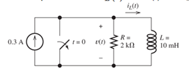
Figure P4.34
Expert Solution & Answer
Want to see the full answer?
Check out a sample textbook solution
Students have asked these similar questions
*P4.34. Consider the circuit shown in Figure P4.34. The initial current in the inductor is i L (0-
)= -0.2 A. Find expressions for i L (t) and v() for t20 and sketch to scale versus time.
R=
2 kl
L=
0.3 A
10 mH
Figure P4.34
The initial capacitor voltage is 4 V. Switch S1 is closed at t = 0. The charge (in micro C) lost by the capacitor form t = 25 microS to t = 100 microS is:1) 6.992) 8.713) 5.554) 10Please show detailed steps and work
Solve for v(t) for t>0 in the circuit of Figure P4.47, given that the inductor current is zero prior to t=0. [Hint: Try a particular solution of the form v p =A cos( 10t )+B sin( 10t ).]
Chapter 4 Solutions
EBK ELECTRICAL ENGINEERING
Ch. 4 - Suppose we have a capacitance C discharging...Ch. 4 - The dielectric materials used in real capacitors...Ch. 4 - The initial voltage across the capacitor shown in...Ch. 4 - A 100F capacitance is initially charged to 1000 V....Ch. 4 - At t = 0, a charged 10{ F capacitance is connected...Ch. 4 - At time t1 , a capacitance C is charged to a...Ch. 4 - Given an initially charged capacitance that begins...Ch. 4 - The initial voltage across the capacitor shown in...Ch. 4 - In physics, the half-life is often used to...Ch. 4 - We know that a 50F capacitance is charged to an...
Ch. 4 - We know that the capacitor shown in Figure P4.11...Ch. 4 - The purchasing power P of a certain unit of...Ch. 4 - Derive an expression for vC(t) in the circuit of...Ch. 4 - Suppose that at t= 0, we connect an uncharged 10 F...Ch. 4 - Suppose we have a capacitance C that is charged to...Ch. 4 - A person shuffling across a dry carpet can be...Ch. 4 - Prob. 4.17PCh. 4 - Consider the circuit shown in Figure P4.18. Prior...Ch. 4 - List the steps for dc steady-state analysis of RLC...Ch. 4 - Explain why we replace capacitances with open...Ch. 4 - Solve for the steady-state values of i1, i2, and...Ch. 4 - Consider the circuit shown in Figure P4.22. What...Ch. 4 - In the circuit of Figure P4.23, the switch is in...Ch. 4 - The circuit shown in Figure P4.24 has been set up...Ch. 4 - Solve for the steady-state values of i1 , i2, i3,...Ch. 4 - The circuit shown in Figure P4.26 is operating in...Ch. 4 - Prob. 4.27PCh. 4 - Consider the circuit of Figure P4.28 in which the...Ch. 4 - For the circuit shown in Figure P4.29, the switch...Ch. 4 - Consider the circuit of Figure P4.30 in which the...Ch. 4 - Give the expression for the time constant of a...Ch. 4 - A circuit consists of switches that open or close...Ch. 4 - The circuit shown in Figure P4.33 is operating in...Ch. 4 - Consider the circuit shown in Figure P4.34. The...Ch. 4 - Repeat Problem P4.34 given iL(0)=0A .Ch. 4 - Real inductors have series resistance associated...Ch. 4 - Determine expressions for and sketch is(t) to...Ch. 4 - For the circuit shown in Figure P4.38,, find an...Ch. 4 - The circuit shown in Figure P4.39 is operating in...Ch. 4 - Consider the circuit shown in Figure P4.40. A...Ch. 4 - Due to components not shown in the figure, the...Ch. 4 - The switch shown in Figure P4.42 has been closed...Ch. 4 - Determine expressions for and sketch vR(t) to...Ch. 4 - What are the steps in solving a circuit having a...Ch. 4 - Prob. 4.45PCh. 4 - Solve for vC(t) for t > 0 in the circuit of Figure...Ch. 4 - Solve for v(t) for t > 0 in the circuit of Figure...Ch. 4 - Prob. 4.48PCh. 4 - Consider the circuit shown inFigure P4.49. The...Ch. 4 - Consider the circuit shown in Figure P4.50. The...Ch. 4 - The voltage source shown in Figure P4.51 is called...Ch. 4 - Determine the form of the particular solution for...Ch. 4 - Determine the form of the particular solution for...Ch. 4 - Prob. 4.54PCh. 4 - Prob. 4.55PCh. 4 - How can first-or second-order circuits be...Ch. 4 - Prob. 4.57PCh. 4 - Prob. 4.58PCh. 4 - Prob. 4.59PCh. 4 - Sketch a step response for a second-order system...Ch. 4 - A dc source is connected to a series RLC circuit...Ch. 4 - Repeat Problem P4.61 for R = 40 .Ch. 4 - Repeat Problem P4.61 for R = 20 .Ch. 4 - Prob. 4.64PCh. 4 - Repeat Problem P4.64 for R=50 .Ch. 4 - Repeat Problem P4.64 for R=500 .Ch. 4 - Solve for i(t) for t > 0 in the circuit of Figure...Ch. 4 - Prob. 4.68PCh. 4 - Prob. 4.69PCh. 4 - Prob. 4.70PCh. 4 - Use MATLAB to derive an expression for vc(t)in the...Ch. 4 - Prob. 4.72PCh. 4 - Consider the circuit shown in FigureP4.50 in which...Ch. 4 - Prob. 4.74PCh. 4 - Prob. 4.75PCh. 4 - Use MATLAB to solve for the mesh currents in the...Ch. 4 - The switch m the circuit shown in Figure T4.1 is...Ch. 4 - Prob. 4.2PTCh. 4 - Consider the circuit shown in Figure T4.3. Figure...Ch. 4 - Consider the circuit shown in Figure T4.4 in which...Ch. 4 - Write the MATLAB commands to obtain the solution...
Knowledge Booster


Learn more about
Need a deep-dive on the concept behind this application? Look no further. Learn more about this topic, electrical-engineering and related others by exploring similar questions and additional content below.Similar questions
- P4.34. Consider the circuit shown in Figure P4.34. The initial current in the inductor is iL (0-) 0. Find expressions for i (t) and v(t) for t> 0 and sketch to scale versus time. 0.1 A (1) R = v(t) 1 k2 t = 0 1 mH Figure P4.34arrow_forwardWhen a switch is closed in a cirvuit containing a battery E,a resistance R and an inductance L,the current i build up at rate given by L di/dt +Ri=E.find "i" as a function "t"arrow_forwardThe capacitor behaves as an open circuit to a DC source. Why? How does the inductor behave to a DC source? Please explain in great detail.arrow_forward
- The circuit shown in Figure P4.39 is operating in steady state with the switch closed prior to t=0. Find expressions for i L ( t ) for t<0 and for t≥0. Sketch iL(t) to scale versus timearrow_forwardDerive the equivalent circuit for a parallel connection of ideal capacitors. Assume that the initial voltage across the paralleled capacitors is v(t0). (Hint: Sum the currents into the string of capacitors, recognizing that the parallel connection forces the voltage across each capacitor to be the same.)arrow_forwardP4.44. What are the steps in solving a circuit having a resistance, a source, and an inductance (or capacitance)? *P4.45.) Write the differential equation for i(t) and find the complete solution for the circuit of Figure P4.45. [Hint: Try a particular solution of the form ip(t) =Ae-!] %3D 10 H 5et i(t) 5Ω Figure P4.45 P14arrow_forward
- 4.4 25 25. A capacitor (0.02 F) is charged to 1 V and then connected in series with an inductor (10 H) and a resistor (40 S2). Ini- tially, there is no current in the circuit. Find the amplitude, frequency, and phase of the charge on the capacitor and plot its graph.arrow_forwardGiven circuit below, use superposition to find voltage across the capacitor, vclt). Frequency is 100 Hz. 6kn 4kn reee zkn O SmA <45 Vc (t) DC a) Given circuit below and switch ciosed for long time, what is the value of Vc? 5mA 3 luk bị At0, switch is opened. Write a mathematical expression for Velt) after opening of the switch. Evaluate this voltage at te10 ms. Attach File Browse Local Fies rowie Conent Cotection 74°Farrow_forwardFor the circuit in the figure, initially the switch S is closed in (b), until the capacitor is charged; then the switch goes to point (a) so that the battery is disconnected and the capacitor, resistor and inductor are connected in series. Once S is connected at point (a), find a) the angular frequency of oscillation for the series circuit b) write the equation for the charge on the capacitor as a function of time with the respective values of Qmax, angular frequency Wd and time T c) make the Q(t) graph showing explicitly the envelope of the exponential decay (Hint: use geogebra or an application of your choice to obtain a graph).arrow_forward
- The circuit shown consists of four capacitors, an ideal battery of emf &, a switch 'S' and an inductor of inductance L. The switch Sis kept open for a long time. Find the maximum current through the inductor after the switch 'S' is closed. 2C 4C C S 8 3C =8arrow_forwardSolve the circuit by obtaining the state equation. The initial condition voltage value of the capacitance element is VC (0) = 1Volt. R1 = R2 = R3 = R4 = 1Ω, E = 3Volt. State the core solution and the forced solution components in the solution you obtained.arrow_forwardFor the circuit, now keep switch J2 closed, close switch J1. Determine the expressions for the voltage across the capacitor and the current delivered by the source. Find the time it takes for the capacitor to reach its final voltage and what value it is.arrow_forward
arrow_back_ios
SEE MORE QUESTIONS
arrow_forward_ios
Recommended textbooks for you
 Introductory Circuit Analysis (13th Edition)Electrical EngineeringISBN:9780133923605Author:Robert L. BoylestadPublisher:PEARSON
 Delmar's Standard Textbook Of ElectricityElectrical EngineeringISBN:9781337900348Author:Stephen L. HermanPublisher:Cengage Learning
 Programmable Logic ControllersElectrical EngineeringISBN:9780073373843Author:Frank D. PetruzellaPublisher:McGraw-Hill Education
 Fundamentals of Electric CircuitsElectrical EngineeringISBN:9780078028229Author:Charles K Alexander, Matthew SadikuPublisher:McGraw-Hill Education
 Electric Circuits. (11th Edition)Electrical EngineeringISBN:9780134746968Author:James W. Nilsson, Susan RiedelPublisher:PEARSON
 Engineering ElectromagneticsElectrical EngineeringISBN:9780078028151Author:Hayt, William H. (william Hart), Jr, BUCK, John A.Publisher:Mcgraw-hill Education,
Introductory Circuit Analysis (13th Edition)
Electrical Engineering
ISBN:9780133923605
Author:Robert L. Boylestad
Publisher:PEARSON
Delmar's Standard Textbook Of Electricity
Electrical Engineering
ISBN:9781337900348
Author:Stephen L. Herman
Publisher:Cengage Learning
Programmable Logic Controllers
Electrical Engineering
ISBN:9780073373843
Author:Frank D. Petruzella
Publisher:McGraw-Hill Education
Fundamentals of Electric Circuits
Electrical Engineering
ISBN:9780078028229
Author:Charles K Alexander, Matthew Sadiku
Publisher:McGraw-Hill Education
Electric Circuits. (11th Edition)
Electrical Engineering
ISBN:9780134746968
Author:James W. Nilsson, Susan Riedel
Publisher:PEARSON
Engineering Electromagnetics
Electrical Engineering
ISBN:9780078028151
Author:Hayt, William H. (william Hart), Jr, BUCK, John A.
Publisher:Mcgraw-hill Education,
Capacitors Explained - The basics how capacitors work working principle; Author: The Engineering Mindset;https://www.youtube.com/watch?v=X4EUwTwZ110;License: Standard YouTube License, CC-BY