Design of Machinery
6th Edition
ISBN: 9781260431315
Author: Norton, Robert
Publisher: MCGRAW-HILL HIGHER EDUCATION
expand_more
expand_more
format_list_bulleted
Concept explainers
Videos
Textbook Question
Chapter 4, Problem 4.22P
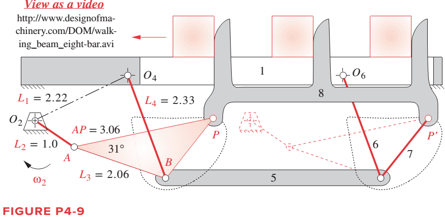
For the walking-beam
Expert Solution & Answer
Want to see the full answer?
Check out a sample textbook solution
Students have asked these similar questions
The link lengths, value of theta2, and offset for some fourbar slider-crank linkages are defined inTable P4-2. The linkage configuration and terminology are shown in Figure P4-2. For row a,draw the linkage to scale and graphically find all possible solutions (both open and crossed)for angles theta3 and slider position d.
Hi I was wondering I could get help with this question.
The linkage in Figure has link 1 at –36° in the global XY coordinate system.Find and plot ω4, VA, and VB inthe local coordinate system for the maximum range of motion that this linkage allows ifω2 = 20 rad/sec CCW.
A general fourbar linkage configuration and its notation are shown in Figure
below. The link lengths, coupler point location, and the values of 02 and
w2 for the same fourbar linkages as used for position analysis in Chapter 4
are redefined in Table below. For the row c, draw the linkage to scale and
Using an analytical method calculate w3 and w4 and find the velocity of
point P. find the velocities of the pin joints A and.
RPA
Y
B
4
03
04
02
1
02
FIGURE P6-1
Configuration and terminology for the pin-jointed fourbar linkage of Problems 6-4 to 6-5
TABLE P6-1
Data for Problems 6-4 to 6-5†
Row
Link 1
Link 2
Link 3
Link 4
02
Rpa
83
02
a
2
7
9.
30
10
30
7
9.
8
85
-12
9
25
3
10
8
45
-15
10
80
Chapter 4 Solutions
Design of Machinery
Ch. 4 - A position vector is defined as having a length...Ch. 4 - A particle is traveling along an arc of 6.5-in...Ch. 4 - Repeat problem 4-2 considering points A and B to...Ch. 4 - Repeat Problem 4-2 with the particles path defined...Ch. 4 - Repeat Problem 4-3 with the path of the particle...Ch. 4 - The link lengths and the value of 2 for some...Ch. 4 - Repeat Problem 4-6 except solve by the vector loop...Ch. 4 - Expand equation 4.7b and prove that it reduces to...Ch. 4 - The link lengths and the value of 2 and offset for...Ch. 4 - Repeat Problem 4-9 except solve by the vector loop...
Ch. 4 - The link lengths and the value of 2 and for some...Ch. 4 - Repeat Problem 4-11 except solve by the vector...Ch. 4 - Find the transmission angles of the linkages in...Ch. 4 - Find the minimum and maximum values of the...Ch. 4 - Find the input angles corresponding to the toggle...Ch. 4 - The link lengths. gear ratio (). phase angle (),...Ch. 4 - Repeat Problem 4-16 except solve by the vector...Ch. 4 - Figure P4-5 shows the mechanisms for the following...Ch. 4 - For one revolution of driving link 2 of the...Ch. 4 - Figure P4-7 shows a power hacksaw, used to cut...Ch. 4 - For the linkage in Figure P4-8, find its limit...Ch. 4 - For the walking-beam mechanism of Figure P4-9,...Ch. 4 - For the linkage in Figure P4-10, calculate and...Ch. 4 - For the linkage in Figure P4-11, calculate and...Ch. 4 - For the linkage in Figure P4-12, find its limit...Ch. 4 - Prob. 4.26PCh. 4 - For the linkage in Figure P4-13, find its limit...Ch. 4 - Prob. 4.28PCh. 4 - For the linkage in Figure P4-15, find its limit...Ch. 4 - For the linkage in Figure P4-15, find its limit...Ch. 4 - Prob. 4.31PCh. 4 - Prob. 4.32PCh. 4 - Figure 4-22 plots the cubic function from equation...Ch. 4 - Write a computer program or use an equation solver...Ch. 4 - Prob. 4.35PCh. 4 - Prob. 4.36PCh. 4 - Write a computer program or use an equation solver...Ch. 4 - Write a computer program or use an equation solver...Ch. 4 - Prob. 4.39PCh. 4 - Prob. 4.40PCh. 4 - Write a computer program or use an equation solver...Ch. 4 - Prob. 4.42PCh. 4 - Prob. 4.43PCh. 4 - Prob. 4.44PCh. 4 - Model the linkage shown in Figure 3-37a in...Ch. 4 - Prob. 4.46PCh. 4 - Prob. 4.47PCh. 4 - Prob. 4.48PCh. 4 - Prob. 4.49PCh. 4 - Prob. 4.50PCh. 4 - Figure 3-29g shows Evans approximate straight-line...Ch. 4 - For the linkage in Figure P4-16, what are the...Ch. 4 - The coordinates of the point P1 on link 4 in...Ch. 4 - Write a computer program or use an equation solver...Ch. 4 - For the linkage in Figure P4-17, calculate the...Ch. 4 - Prob. 4.56PCh. 4 - Prob. 4.57PCh. 4 - The elliptical trammel in Figure P4-18 must be...Ch. 4 - Prob. 4.59PCh. 4 - Prob. 4.60PCh. 4 - Repeat Problem 4-60 except solve by the vector...Ch. 4 - Write a computer program or use an equation solver...Ch. 4 - Write a computer program or use an equation solver...Ch. 4 - Write a computer program or use an equation solver...Ch. 4 - Write a computer program or use an equation solver...Ch. 4 - Figure P4-20 shows a cut-away view of a mechanism...Ch. 4 - For the linkage in Figure 3-32a, calculate and...
Knowledge Booster


Learn more about
Need a deep-dive on the concept behind this application? Look no further. Learn more about this topic, mechanical-engineering and related others by exploring similar questions and additional content below.Similar questions
- A general fourbar linkage configuration and its notation are shown in Figure below. The link lengths, coupler point location, and the values of 02 and w2 for the same fourbar linkages as used for position analysis in Chapter 4 are redefined in Table below. For the row c, draw the linkage to scale and Using an analytical method calculate w3 and w4 and find the velocity of point P. find the velocities of the pin joints A and. RPA AY 2 04 02 04 FIGURE P6-1 Configuration and terminology for the pin-Jointed fourbar linkage of Problems 6-4 to 6-5 TABLE P6-1 Data for Problems 6-4 to 6-5† Row Link 1 Link 2 Link 3 Link 4 02 02 Rpa 83 6. 2 7 30 10 6. 30 b. 9 3 8 85 -12 9. 25 10 6. 8 45 -15 10 80 O73arrow_forward3. The four bars of Figure A are initially free in the plane, then connecting to bars 2, 3 and 4, through their pivots, to bar 1, as shown in figure B. Choose a generalized coordinate system for these bars in design A and, depending on this system, determine the number of degrees of freedom after assembly, as shown in design B y 3 A B Xarrow_forwardWhat is the equivalent root of the system of the figure using the displacement of the block as a generalized coordinatearrow_forward
- A general inverted fourbar slider-crank linkage has links length: link 2 = a = 2, link 4 = c = 4, and link 1= d = 6 in. The input values are 02 = 60°, y = 90°. The linkage configuration and terminology are shown in figure below; note that this figure does not represent the real dimensions of the linkage We need to find the angular positions of link 4 (04), of link 3 (03) and the effective length of link 3 (b) for both open and crossed configurations. 03 Өд В 4 RB 02 02 1 02 04 Choose... For open configuration, the angle 04 measured form X axis CCW in degree = Choose... For open configuration, the angle 03 measured form X axis CCW in degree = Choose... + For open configuration, the absolute value of the effective length of link 3, b = Choose... For crossed configuration, the angle 04 measured form X axis CCW in degree = Choose... For crossed configuration, the angle 03 measured form X axis CCW in degree = Choose... For crossed configuration, the absolute value of the effective length of…arrow_forwardConsider that we have a 3-R robot as shown in the figure below. The lengths of the links are: 11-12-13=2. The position and posture of the tool's center point is Pt (x₁, y₁, α), the driving variables are 01, 02, 03, and the output variables are v,v,, w.. (It is in the initial position) yo 1₁ Y₁ 0₁ Y₂ 12 02 X1 -X2 V3 13 P₁ X3 a Xoarrow_forwardThe kinematic scheme of the mechanism is given. Point C is the center of curvature of the link 3 at the point of the contact. Link 2 is with circular shape with center point B. Find the degrees of freedom.arrow_forward
- The general linkage configuration and terminology for an offset fourbar slider-crank linkage are shown in Figure below. The link lengths and the values of 02 and w2 are defined in. For the row(s) b and c, find the velocities of the pin joints A and B and the velocity of slip at the sliding joint using an analytical method. Draw the linkage to scale and label it before setting up the equations. y A 03 B Y 4 Link 3 A W2 Offset 02 04 = 90° Link 2 X 02 Slider position d TABLE P6-2 Data for Problems 6-6 to 6-7† Row Link 2 Link 3 Offset 02 02 a 1.4 4 1 45 10 2 -3 60 -12 3 8 2 -30 -15arrow_forwardThe general linkage configuration and terminology for an offset fourbar slider-crank linkage are shown in Figure below. The link lengths and the values of 02 and w2 are defined in. For the row(s) b and c, find the velocities of the pin joints A and B and the velocity of slip at the sliding joint using an analytical method. Draw the linkage to scale and label it before setting up the equations. Link 3 Offset 04 = 90° Link 2 02 Slider position d TABLE P6-2 Data for Problems 6-6 to 6-7† Row Link 2 Link 3 Offset 02 1.4 4 1. 45 10 2 6. -3 60 -12 3 8. -30 -15arrow_forwardPlz answer this question Given the vectors in Figure P1-2 using a scale of 1 inch = 10 units, and determine the following vectors on the image below: Additional information A= 20 B= 270⁰ ; 10 C=210⁰ ; 15 D=315⁰; 12,5 E=75⁰ ; 7,5 F=215⁰ ; 10 G=100⁰ ; 15arrow_forward
- Use rotation about the current frame to calculate the transformation matrix for a rotation of 90° about yo axis and then 90° about zo axis.arrow_forwardThe linkage in Figure P7-5b has 04A = O2A = 0.75 , AB = 1.5 , and AC = 1.2 in . The effective crank angle in the position shown is 77º and angle BAC = 30 ° . Find a3 , AA , AB , Ac for the position shown for m2 = 15 rad / sec and a2 = 10 rad / sec2 in the directions shown using an analytical method . ( Hint : Create an effective linkage for the position shown and analyze it as a pin - jointed fourbar . ) the linkage has a parallelogram form Assume rolling contact C 02 A 3 . B 02 02 Tarrow_forwardGiven the vectors in Figure P1-2, use a scale of 1 inch = 10 units, and determine the following vectors: Figure P1-2 B=10 ; 270⁰ C=15 ; 210⁰ D=12,5 ; 315⁰ E= 7,5 ; 75⁰ F = 10 ; 215⁰ G= 15 ; 100⁰arrow_forward
arrow_back_ios
SEE MORE QUESTIONS
arrow_forward_ios
Recommended textbooks for you
 Elements Of ElectromagneticsMechanical EngineeringISBN:9780190698614Author:Sadiku, Matthew N. O.Publisher:Oxford University Press
 Mechanics of Materials (10th Edition)Mechanical EngineeringISBN:9780134319650Author:Russell C. HibbelerPublisher:PEARSON
 Thermodynamics: An Engineering ApproachMechanical EngineeringISBN:9781259822674Author:Yunus A. Cengel Dr., Michael A. BolesPublisher:McGraw-Hill Education
 Control Systems EngineeringMechanical EngineeringISBN:9781118170519Author:Norman S. NisePublisher:WILEY
 Mechanics of Materials (MindTap Course List)Mechanical EngineeringISBN:9781337093347Author:Barry J. Goodno, James M. GerePublisher:Cengage Learning
 Engineering Mechanics: StaticsMechanical EngineeringISBN:9781118807330Author:James L. Meriam, L. G. Kraige, J. N. BoltonPublisher:WILEY
Elements Of Electromagnetics
Mechanical Engineering
ISBN:9780190698614
Author:Sadiku, Matthew N. O.
Publisher:Oxford University Press
Mechanics of Materials (10th Edition)
Mechanical Engineering
ISBN:9780134319650
Author:Russell C. Hibbeler
Publisher:PEARSON
Thermodynamics: An Engineering Approach
Mechanical Engineering
ISBN:9781259822674
Author:Yunus A. Cengel Dr., Michael A. Boles
Publisher:McGraw-Hill Education
Control Systems Engineering
Mechanical Engineering
ISBN:9781118170519
Author:Norman S. Nise
Publisher:WILEY
Mechanics of Materials (MindTap Course List)
Mechanical Engineering
ISBN:9781337093347
Author:Barry J. Goodno, James M. Gere
Publisher:Cengage Learning
Engineering Mechanics: Statics
Mechanical Engineering
ISBN:9781118807330
Author:James L. Meriam, L. G. Kraige, J. N. Bolton
Publisher:WILEY
LIMITS FITS AND TOLERANCES: What is limit fit & tolerance and its need? Animation; Author: ADTW learn;https://www.youtube.com/watch?v=joBy4BoJszo;License: Standard YouTube License, CC-BY
Limits and Continuity; Author: The Organic Chemistry Tutor;https://www.youtube.com/watch?v=9brk313DjV8;License: Standard YouTube License, CC-BY