Design of Machinery
6th Edition
ISBN: 9781260431315
Author: Norton, Robert
Publisher: MCGRAW-HILL HIGHER EDUCATION
expand_more
expand_more
format_list_bulleted
Videos
Textbook Question
Chapter 4, Problem 4.24P
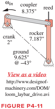
For the linkage in Figure P4-11, calculate and plot the angular displacement of links 3 and 4 with respect to the angle of the input crank
Expert Solution & Answer

Trending nowThis is a popular solution!

Students have asked these similar questions
For the walking-beam mechanism of Figure P4-9, calculate and plot the xand y components of the position of the coupler point P for one complete revolution of the crank O2A. Hint: Calculate them first with respect to the ground link O204 and then transform them into the global XY coordinate system (i.e., horizontal and vertical in the figure). Scale the figure for any additional information needed
The linkage in Figure P7-5b has 04A = O2A = 0.75 , AB = 1.5 , and AC = 1.2 in . The effective crank angle in the position shown is 77º and angle BAC = 30 ° . Find a3 , AA , AB , Ac for the position shown for m2 = 15 rad / sec and a2 = 10 rad / sec2 in the directions shown using an analytical method . ( Hint : Create an effective linkage for the position shown and analyze it as a pin - jointed fourbar . ) the linkage has a parallelogram form Assume rolling contact C 02 A 3 . B 02 02 T
Problem 2
The linkage in Figure P7-5b has O,A = O2A = 0.75, AB= 1.5, and AC = 1.2
in. The effective crank angle in the position shown is 77° and angle BAC =
30°. Find a3, A4, AB,Ac for the position shown for @2 = 15 rad/sec and a2 =
10 rad/sec in the directions shown using an analytical method.
(Hint: Create an effective linkage for the position shown and analyze it as a
pin-jointed fourbar.)the linkage has a parallelogram form
Assume rolling contact
C
@2
A
3
В
a2
2
4
04
Chapter 4 Solutions
Design of Machinery
Ch. 4 - A position vector is defined as having a length...Ch. 4 - A particle is traveling along an arc of 6.5-in...Ch. 4 - Repeat problem 4-2 considering points A and B to...Ch. 4 - Repeat Problem 4-2 with the particles path defined...Ch. 4 - Repeat Problem 4-3 with the path of the particle...Ch. 4 - The link lengths and the value of 2 for some...Ch. 4 - Repeat Problem 4-6 except solve by the vector loop...Ch. 4 - Expand equation 4.7b and prove that it reduces to...Ch. 4 - The link lengths and the value of 2 and offset for...Ch. 4 - Repeat Problem 4-9 except solve by the vector loop...
Ch. 4 - The link lengths and the value of 2 and for some...Ch. 4 - Repeat Problem 4-11 except solve by the vector...Ch. 4 - Find the transmission angles of the linkages in...Ch. 4 - Find the minimum and maximum values of the...Ch. 4 - Find the input angles corresponding to the toggle...Ch. 4 - The link lengths. gear ratio (). phase angle (),...Ch. 4 - Repeat Problem 4-16 except solve by the vector...Ch. 4 - Figure P4-5 shows the mechanisms for the following...Ch. 4 - For one revolution of driving link 2 of the...Ch. 4 - Figure P4-7 shows a power hacksaw, used to cut...Ch. 4 - For the linkage in Figure P4-8, find its limit...Ch. 4 - For the walking-beam mechanism of Figure P4-9,...Ch. 4 - For the linkage in Figure P4-10, calculate and...Ch. 4 - For the linkage in Figure P4-11, calculate and...Ch. 4 - For the linkage in Figure P4-12, find its limit...Ch. 4 - Prob. 4.26PCh. 4 - For the linkage in Figure P4-13, find its limit...Ch. 4 - Prob. 4.28PCh. 4 - For the linkage in Figure P4-15, find its limit...Ch. 4 - For the linkage in Figure P4-15, find its limit...Ch. 4 - Prob. 4.31PCh. 4 - Prob. 4.32PCh. 4 - Figure 4-22 plots the cubic function from equation...Ch. 4 - Write a computer program or use an equation solver...Ch. 4 - Prob. 4.35PCh. 4 - Prob. 4.36PCh. 4 - Write a computer program or use an equation solver...Ch. 4 - Write a computer program or use an equation solver...Ch. 4 - Prob. 4.39PCh. 4 - Prob. 4.40PCh. 4 - Write a computer program or use an equation solver...Ch. 4 - Prob. 4.42PCh. 4 - Prob. 4.43PCh. 4 - Prob. 4.44PCh. 4 - Model the linkage shown in Figure 3-37a in...Ch. 4 - Prob. 4.46PCh. 4 - Prob. 4.47PCh. 4 - Prob. 4.48PCh. 4 - Prob. 4.49PCh. 4 - Prob. 4.50PCh. 4 - Figure 3-29g shows Evans approximate straight-line...Ch. 4 - For the linkage in Figure P4-16, what are the...Ch. 4 - The coordinates of the point P1 on link 4 in...Ch. 4 - Write a computer program or use an equation solver...Ch. 4 - For the linkage in Figure P4-17, calculate the...Ch. 4 - Prob. 4.56PCh. 4 - Prob. 4.57PCh. 4 - The elliptical trammel in Figure P4-18 must be...Ch. 4 - Prob. 4.59PCh. 4 - Prob. 4.60PCh. 4 - Repeat Problem 4-60 except solve by the vector...Ch. 4 - Write a computer program or use an equation solver...Ch. 4 - Write a computer program or use an equation solver...Ch. 4 - Write a computer program or use an equation solver...Ch. 4 - Write a computer program or use an equation solver...Ch. 4 - Figure P4-20 shows a cut-away view of a mechanism...Ch. 4 - For the linkage in Figure 3-32a, calculate and...
Knowledge Booster


Learn more about
Need a deep-dive on the concept behind this application? Look no further. Learn more about this topic, mechanical-engineering and related others by exploring similar questions and additional content below.Similar questions
- The kinematic scheme of the mechanism is given. Point C is the center of curvature of the link 3 at the point of the contact. Link 2 is with circular shape with center point B. Find the degrees of freedom.arrow_forwardProblem 2 The linkage in Figure P7-5b has o4A = o2A = 0.75, AB = 1.5, and AC = 1.2 in. The effective crank angle in the position shown is 77° and angle BAC = 30°. Find a3, AA, AB, Ac for the position shown for w2 = 15 rad/sec and a2 = 10 rad/sec^2 in the directions shown using an analytic method. (Hint: Create an effective linkage for the position shown and analyze it as a pin-jointed fourbar.) the linkage has a parallelogram form Assume rolling contactarrow_forwardProblem 2 The linkage in Figure P7-5b has O4A = O2A = 0.75, AB = 1.5, and AC = 1.2 in. The effective crank angle in the position shown is 77° and angle BAC = 30°. Find a3, AA. AB,Ac for the position shown for w2 = 15 rad/sec and a2 = 10 rad/sec^2 in the directions shown using an analytic method. (Hint: Create an effective linkage for the position shown and analyze it as a pin-jointed fourbar.)the linkage has a parallelogram form Assume rolling contactarrow_forward
- Problem 4-6a The link lengths (a, b, c, d) and the value of 2 for a crank-rocker linkage are defined as 2, 7, 9, 6, 30°, respectively. Draw the scaled linkage. Find all possible solutions (both open and crossed) for angles 03 and 04 graphically. Орen B A LNCS 4 a GCS र 4 4" Crossed (This is not the scaled kinematic diagram.) Problem 4-7a Repeat Problem 4-6a except solve by the vector loop method.arrow_forwardDraw the Kinematic Diagram of the following Mechanism (label the links andjoints). Then, calculate their Degree of Freedom.arrow_forwardA general fourbar linkage configuration and its notation are shown in Figure below. The link lengths, coupler point location, and the values of 02 and w2 for the same fourbar linkages as used for position analysis in Chapter 4 are redefined in Table below. For the row c, draw the linkage to scale and Using an analytical method calculate w3 and w4 and find the velocity of point P. find the velocities of the pin joints A and. RPA Y B 4 03 04 02 1 02 FIGURE P6-1 Configuration and terminology for the pin-jointed fourbar linkage of Problems 6-4 to 6-5 TABLE P6-1 Data for Problems 6-4 to 6-5† Row Link 1 Link 2 Link 3 Link 4 02 Rpa 83 02 a 2 7 9. 30 10 30 7 9. 8 85 -12 9 25 3 10 8 45 -15 10 80arrow_forward
- A general fourbar linkage configuration and its notation are shown in Figure below. The link lengths, coupler point location, and the values of 02 and w2 for the same fourbar linkages as used for position analysis in Chapter 4 are redefined in Table below. For the row c, draw the linkage to scale and Using an analytical method calculate w3 and w4 and find the velocity of point P. find the velocities of the pin joints A and. RPA AY 2 04 02 04 FIGURE P6-1 Configuration and terminology for the pin-Jointed fourbar linkage of Problems 6-4 to 6-5 TABLE P6-1 Data for Problems 6-4 to 6-5† Row Link 1 Link 2 Link 3 Link 4 02 02 Rpa 83 6. 2 7 30 10 6. 30 b. 9 3 8 85 -12 9. 25 10 6. 8 45 -15 10 80 O73arrow_forward3. The four bars of Figure A are initially free in the plane, then connecting to bars 2, 3 and 4, through their pivots, to bar 1, as shown in figure B. Choose a generalized coordinate system for these bars in design A and, depending on this system, determine the number of degrees of freedom after assembly, as shown in design B y 3 A B Xarrow_forwardDraw the kinematic digrams of the following mechanisms and compute the number of Degreesof Freedom (Mobility) of the figure belowarrow_forward
- A general inverted fourbar slider-crank linkage has links length: link 2 = a = 2, link 4 = c = 4, and link 1= d = 6 in. The input values are 02 = 60°, y = 90°. The linkage configuration and terminology are shown in figure below; note that this figure does not represent the real dimensions of the linkage We need to find the angular positions of link 4 (04), of link 3 (03) and the effective length of link 3 (b) for both open and crossed configurations. 03 Өд В 4 RB 02 02 1 02 04 Choose... For open configuration, the angle 04 measured form X axis CCW in degree = Choose... For open configuration, the angle 03 measured form X axis CCW in degree = Choose... + For open configuration, the absolute value of the effective length of link 3, b = Choose... For crossed configuration, the angle 04 measured form X axis CCW in degree = Choose... For crossed configuration, the angle 03 measured form X axis CCW in degree = Choose... For crossed configuration, the absolute value of the effective length of…arrow_forwardFigure below shows a four-bar linkage (non-scaled diagram) at an instant. The input angle is equal to the output angle (02 - 04) and the transmission angle is 30°. The input link is extended beyond joint B and an input force (Fin) is applied at the end of it, while an output force is drawn from the midpoint of the output link. If an output force of 30 N is desired from an input force of 10 N, how far the input link should be extended, i.e., what is the distance from point B to the point where Fin is applied. Fin B out undefined 02 04 A. Non-scaled diagram; AB = 10, CD=r4 = 30 (output), all in mmarrow_forwardQ2/ In the toggle mechanism shown in figure below, D is constrained to move on a horizontal path. The dimensions of various links are as follows: Q:45 AB = 200 mm; BC = 300 mm; OC = 150 mm; and BD = 450 mm. 300 mm The crank OC is rotating in a counter clockwise direction at a speed of 18p rpm. Find the velocity of D, and angular velocity of BD.arrow_forward
arrow_back_ios
SEE MORE QUESTIONS
arrow_forward_ios
Recommended textbooks for you
 Elements Of ElectromagneticsMechanical EngineeringISBN:9780190698614Author:Sadiku, Matthew N. O.Publisher:Oxford University Press
 Mechanics of Materials (10th Edition)Mechanical EngineeringISBN:9780134319650Author:Russell C. HibbelerPublisher:PEARSON
 Thermodynamics: An Engineering ApproachMechanical EngineeringISBN:9781259822674Author:Yunus A. Cengel Dr., Michael A. BolesPublisher:McGraw-Hill Education
 Control Systems EngineeringMechanical EngineeringISBN:9781118170519Author:Norman S. NisePublisher:WILEY
 Mechanics of Materials (MindTap Course List)Mechanical EngineeringISBN:9781337093347Author:Barry J. Goodno, James M. GerePublisher:Cengage Learning
 Engineering Mechanics: StaticsMechanical EngineeringISBN:9781118807330Author:James L. Meriam, L. G. Kraige, J. N. BoltonPublisher:WILEY
Elements Of Electromagnetics
Mechanical Engineering
ISBN:9780190698614
Author:Sadiku, Matthew N. O.
Publisher:Oxford University Press
Mechanics of Materials (10th Edition)
Mechanical Engineering
ISBN:9780134319650
Author:Russell C. Hibbeler
Publisher:PEARSON
Thermodynamics: An Engineering Approach
Mechanical Engineering
ISBN:9781259822674
Author:Yunus A. Cengel Dr., Michael A. Boles
Publisher:McGraw-Hill Education
Control Systems Engineering
Mechanical Engineering
ISBN:9781118170519
Author:Norman S. Nise
Publisher:WILEY
Mechanics of Materials (MindTap Course List)
Mechanical Engineering
ISBN:9781337093347
Author:Barry J. Goodno, James M. Gere
Publisher:Cengage Learning
Engineering Mechanics: Statics
Mechanical Engineering
ISBN:9781118807330
Author:James L. Meriam, L. G. Kraige, J. N. Bolton
Publisher:WILEY
Polymer Basics; Author: Tonya Coffey;https://www.youtube.com/watch?v=c5gFHpWvDXk;License: Standard youtube license