Design of Machinery
6th Edition
ISBN: 9781260431315
Author: Norton, Robert
Publisher: MCGRAW-HILL HIGHER EDUCATION
expand_more
expand_more
format_list_bulleted
Videos
Textbook Question
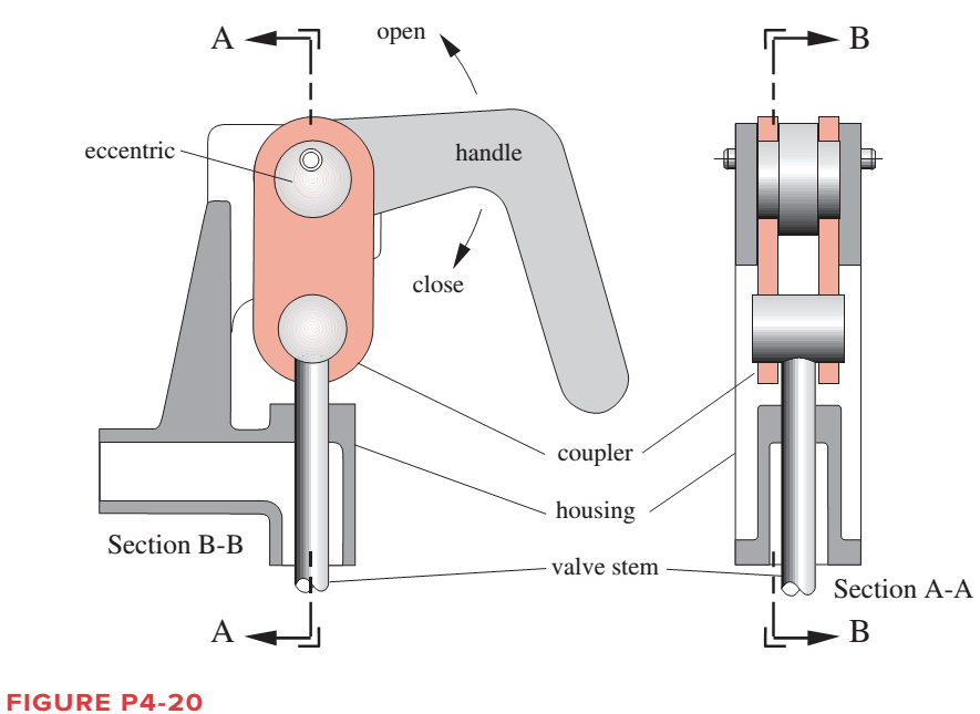
Chapter 4, Problem 4.66P
Figure P4-20 shows a cut-away view of a
Expert Solution & Answer
Want to see the full answer?
Check out a sample textbook solution
Students have asked these similar questions
Problem 2
The linkage in Figure P7-5b has O,A = O2A = 0.75, AB= 1.5, and AC = 1.2
in. The effective crank angle in the position shown is 77° and angle BAC =
30°. Find a3, A4, AB,Ac for the position shown for @2 = 15 rad/sec and a2 =
10 rad/sec in the directions shown using an analytical method.
(Hint: Create an effective linkage for the position shown and analyze it as a
pin-jointed fourbar.)the linkage has a parallelogram form
Assume rolling contact
C
@2
A
3
В
a2
2
4
04
For the walking-beam mechanism of Figure P4-9, calculate and plot the xand y components of the position of the coupler point P for one complete revolution of the crank O2A. Hint: Calculate them first with respect to the ground link O204 and then transform them into the global XY coordinate system (i.e., horizontal and vertical in the figure). Scale the figure for any additional information needed
Problem 4-9a
The link lengths and offset (a, b, c) and the value of 02 for an offset crank-slider linkage
are defined as 1.4 in, 4 in, 1 in, 45°, respectively. Draw the scaled linkage and graphically
find all possible solutions (both open and crossed) for angle 0z and slide position d.
- slider axis
B
R3
A
R4
offset
R,
04
02
(This is not the scaled kinematic diagram.)
Problem 4-10a
Repeat Problem 4-9a except solve by the vector loop method.
Chapter 4 Solutions
Design of Machinery
Ch. 4 - A position vector is defined as having a length...Ch. 4 - A particle is traveling along an arc of 6.5-in...Ch. 4 - Repeat problem 4-2 considering points A and B to...Ch. 4 - Repeat Problem 4-2 with the particles path defined...Ch. 4 - Repeat Problem 4-3 with the path of the particle...Ch. 4 - The link lengths and the value of 2 for some...Ch. 4 - Repeat Problem 4-6 except solve by the vector loop...Ch. 4 - Expand equation 4.7b and prove that it reduces to...Ch. 4 - The link lengths and the value of 2 and offset for...Ch. 4 - Repeat Problem 4-9 except solve by the vector loop...
Ch. 4 - The link lengths and the value of 2 and for some...Ch. 4 - Repeat Problem 4-11 except solve by the vector...Ch. 4 - Find the transmission angles of the linkages in...Ch. 4 - Find the minimum and maximum values of the...Ch. 4 - Find the input angles corresponding to the toggle...Ch. 4 - The link lengths. gear ratio (). phase angle (),...Ch. 4 - Repeat Problem 4-16 except solve by the vector...Ch. 4 - Figure P4-5 shows the mechanisms for the following...Ch. 4 - For one revolution of driving link 2 of the...Ch. 4 - Figure P4-7 shows a power hacksaw, used to cut...Ch. 4 - For the linkage in Figure P4-8, find its limit...Ch. 4 - For the walking-beam mechanism of Figure P4-9,...Ch. 4 - For the linkage in Figure P4-10, calculate and...Ch. 4 - For the linkage in Figure P4-11, calculate and...Ch. 4 - For the linkage in Figure P4-12, find its limit...Ch. 4 - Prob. 4.26PCh. 4 - For the linkage in Figure P4-13, find its limit...Ch. 4 - Prob. 4.28PCh. 4 - For the linkage in Figure P4-15, find its limit...Ch. 4 - For the linkage in Figure P4-15, find its limit...Ch. 4 - Prob. 4.31PCh. 4 - Prob. 4.32PCh. 4 - Figure 4-22 plots the cubic function from equation...Ch. 4 - Write a computer program or use an equation solver...Ch. 4 - Prob. 4.35PCh. 4 - Prob. 4.36PCh. 4 - Write a computer program or use an equation solver...Ch. 4 - Write a computer program or use an equation solver...Ch. 4 - Prob. 4.39PCh. 4 - Prob. 4.40PCh. 4 - Write a computer program or use an equation solver...Ch. 4 - Prob. 4.42PCh. 4 - Prob. 4.43PCh. 4 - Prob. 4.44PCh. 4 - Model the linkage shown in Figure 3-37a in...Ch. 4 - Prob. 4.46PCh. 4 - Prob. 4.47PCh. 4 - Prob. 4.48PCh. 4 - Prob. 4.49PCh. 4 - Prob. 4.50PCh. 4 - Figure 3-29g shows Evans approximate straight-line...Ch. 4 - For the linkage in Figure P4-16, what are the...Ch. 4 - The coordinates of the point P1 on link 4 in...Ch. 4 - Write a computer program or use an equation solver...Ch. 4 - For the linkage in Figure P4-17, calculate the...Ch. 4 - Prob. 4.56PCh. 4 - Prob. 4.57PCh. 4 - The elliptical trammel in Figure P4-18 must be...Ch. 4 - Prob. 4.59PCh. 4 - Prob. 4.60PCh. 4 - Repeat Problem 4-60 except solve by the vector...Ch. 4 - Write a computer program or use an equation solver...Ch. 4 - Write a computer program or use an equation solver...Ch. 4 - Write a computer program or use an equation solver...Ch. 4 - Write a computer program or use an equation solver...Ch. 4 - Figure P4-20 shows a cut-away view of a mechanism...Ch. 4 - For the linkage in Figure 3-32a, calculate and...
Knowledge Booster


Learn more about
Need a deep-dive on the concept behind this application? Look no further. Learn more about this topic, mechanical-engineering and related others by exploring similar questions and additional content below.Similar questions
- The linkage in Figure P7-5b has 04A = O2A = 0.75 , AB = 1.5 , and AC = 1.2 in . The effective crank angle in the position shown is 77º and angle BAC = 30 ° . Find a3 , AA , AB , Ac for the position shown for m2 = 15 rad / sec and a2 = 10 rad / sec2 in the directions shown using an analytical method . ( Hint : Create an effective linkage for the position shown and analyze it as a pin - jointed fourbar . ) the linkage has a parallelogram form Assume rolling contact C 02 A 3 . B 02 02 Tarrow_forwardProblem 4.7 ( example on analytical position analysis of pinjointed fourbar linkage) The link lengths and the value of 0, for some fourbar linkages are defined in Table P4-1. 1. For row a, find all possible solutions (both open and crossed) for angles 0, and 0, using the vector loop method. R3 R4 R2 R1 04 FIGURE 4-6arrow_forwardProblem 2 The linkage in Figure P7-5b has o4A = o2A = 0.75, AB = 1.5, and AC = 1.2 in. The effective crank angle in the position shown is 77° and angle BAC = 30°. Find a3, AA, AB, Ac for the position shown for w2 = 15 rad/sec and a2 = 10 rad/sec^2 in the directions shown using an analytic method. (Hint: Create an effective linkage for the position shown and analyze it as a pin-jointed fourbar.) the linkage has a parallelogram form Assume rolling contactarrow_forward
- Figure below shows a four-bar linkage (non-scaled diagram) at an instant. The input angle is equal to the output angle (02 - 04) and the transmission angle is 30°. The input link is extended beyond joint B and an input force (Fin) is applied at the end of it, while an output force is drawn from the midpoint of the output link. If an output force of 30 N is desired from an input force of 10 N, how far the input link should be extended, i.e., what is the distance from point B to the point where Fin is applied. Fin B out undefined 02 04 A. Non-scaled diagram; AB = 10, CD=r4 = 30 (output), all in mmarrow_forwardConsider the 2-position design problem depicted below. The mechanism is GRCR. The linklengths and the positions of anchor points O1 and O2 are provided.a. Do any toggle positions exist between configurations CD and C’D’ that would prevent themechanism from completing the motion? If so, at what angle(s) of θ do they occur?b. Find new values for the coordinates (X,Y) of O2 that would enable the mechanism to bedriven by a driver dyad attached to link O1C, e.g., point B.c. What are the coordinates (X,Y) of O2 closest to the origin for which the mechanism canstill be driven by a driver dyad attached to link O1C, e.g., point B, as in part b?arrow_forwardOestion-1: An elliptical trammel is a double slider-crank mechanism used for drawing ellipses as shown in figure (a) below. Position vectors for various linkages are drawn as shown in figure (b). Where: R2: represents position vector for a Slider which can slide along x-axis only R4: represents position vector for a Slider which can slide along y-axis only R3 represents position vector for a crank (Take R3 = 10mm, 03 = 45°, V3 = 10mm/sec) Rix: This is aligned with x-axis and represents fixed position of slider (R4) from ground RIY: This is aligned with Y-axis and represents fixed position of slider (R2) from ground Take: R13= 20mm, Rịy=40mm. Assume crank is rotating with constant velocity Note: all angles are measured counterclockwise from x-axis. a) Formulate the vector loop, position, velocity and acceleration equations b) Simplify the equations by plugging in respective angles and solve to find R2, R4, linear velocities of both sliders and angular acceleration of crank. c) Identify…arrow_forward
- The figure below shows an offset slider crank linkage. The links lengths are: link2 = a= 100 mm and link3 = b = 600 mm. The offset is c = 190 mm. we need to : 1. determine the maximum horizontal position of the slider B (dmax) and the corresponding input angle 02 2. determine the minimum horizontal position of the slider B (dmin) and the corresponding input angle 02 Y 03 y В R3 R4 R, 04 R2 02 d ► X R1 The maximum horizontal position of the slider is dmax = Choose... + The input angle 02 corresponding to dmax , in degree and measured CCW from X axis, is = Choose... + The minimum horizontal position of the slider is dmin = Choose... + The input angle 02 corresponding to dmin , in degree and measured CcW from X axis, is = Choose.. +arrow_forwardDesign a fourbar linkage for a windshield wiper mechanism such that the wiper blade moves between the two positions (CD, C'D') spending equal time back and forth. The ground link to which the crank is attached must be located within the shaded region shown on bottom right. Verify that the linkage is Grashof.arrow_forwardThe kinematic scheme of the mechanism is given. Point C is the center of curvature of the link 3 at the point of the contact. Link 2 is with circular shape with center point B. Find the degrees of freedom.arrow_forward
- 1. Find a combination of link lengths where motion of a point on output link is one quarter of a circle. 2. Find the value of all 0, 0, 0, and y in open and close configuration Read the value of link lengths and the input angle 8., then use the formulae given below to calculate the value of unknowns 03, 0, and y K₁ = = K₂= d K2 K3 = a²-b²+c²+d² 2ac A = cos 0₂ - K₁ - K₂ cos 0₂ + K3 B = -2 sin 0₂ C = K₁ (K₂ + 1) cos 02 + K3 -B± √B²-4AC 2A 0412 = 2tan-1 d K₁ = — K5 = c²d²a²-6² 2ab D = cos 0₂ - K₁ - K4 cos 0₂ + K5 E = -2 sin 0₂ FK₁+ (K₁ - 1) cos 02 +K5 0312 2 tan-1 (-E± -E± √E²4DF 2D Y = 04-03arrow_forwardProblem 4-6a The link lengths (a, b, c, d) and the value of 62 for a crank-rocker linkage are defined as 2, 7, 9, 6, 30°, respectively. Draw the scaled linkage. Find all possible solutions (both open and crossed) for angles 03 and 04 graphically. Open B 3 A LNCS 4 04 GCS O4 Crossed (This is not the scaled kinematic diagram.) Problem 4-7a Repeat Problem 4-6a except solve by the vector loop method.arrow_forwardPosition Analysis of the crank-slider linkage. The link length and offset for a fourbar slider-crank linkage are: link 2= 3.5, link3= 10, offset=1. Find both open and crossed solutions for angle theta3 and slider position, d, as driver makes a complete revolution.construct graphs to describe how the slider and theta3 varies as theta2 makes the entire revolution.arrow_forward
arrow_back_ios
SEE MORE QUESTIONS
arrow_forward_ios
Recommended textbooks for you
 Elements Of ElectromagneticsMechanical EngineeringISBN:9780190698614Author:Sadiku, Matthew N. O.Publisher:Oxford University Press
 Mechanics of Materials (10th Edition)Mechanical EngineeringISBN:9780134319650Author:Russell C. HibbelerPublisher:PEARSON
 Thermodynamics: An Engineering ApproachMechanical EngineeringISBN:9781259822674Author:Yunus A. Cengel Dr., Michael A. BolesPublisher:McGraw-Hill Education
 Control Systems EngineeringMechanical EngineeringISBN:9781118170519Author:Norman S. NisePublisher:WILEY
 Mechanics of Materials (MindTap Course List)Mechanical EngineeringISBN:9781337093347Author:Barry J. Goodno, James M. GerePublisher:Cengage Learning
 Engineering Mechanics: StaticsMechanical EngineeringISBN:9781118807330Author:James L. Meriam, L. G. Kraige, J. N. BoltonPublisher:WILEY
Elements Of Electromagnetics
Mechanical Engineering
ISBN:9780190698614
Author:Sadiku, Matthew N. O.
Publisher:Oxford University Press
Mechanics of Materials (10th Edition)
Mechanical Engineering
ISBN:9780134319650
Author:Russell C. Hibbeler
Publisher:PEARSON
Thermodynamics: An Engineering Approach
Mechanical Engineering
ISBN:9781259822674
Author:Yunus A. Cengel Dr., Michael A. Boles
Publisher:McGraw-Hill Education
Control Systems Engineering
Mechanical Engineering
ISBN:9781118170519
Author:Norman S. Nise
Publisher:WILEY
Mechanics of Materials (MindTap Course List)
Mechanical Engineering
ISBN:9781337093347
Author:Barry J. Goodno, James M. Gere
Publisher:Cengage Learning
Engineering Mechanics: Statics
Mechanical Engineering
ISBN:9781118807330
Author:James L. Meriam, L. G. Kraige, J. N. Bolton
Publisher:WILEY
Polymer Basics; Author: Tonya Coffey;https://www.youtube.com/watch?v=c5gFHpWvDXk;License: Standard youtube license