
Bundle: Mechanics Of Materials, Loose-leaf Version, 9th + Mindtap Engineering, 1 Term (6 Months) Printed Access Card
9th Edition
ISBN: 9781337594318
Author: Barry J. Goodno; James M. Gere
Publisher: Cengage Learning
expand_more
expand_more
format_list_bulleted
Concept explainers
Videos
Textbook Question
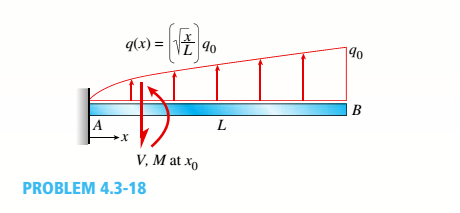
Chapter 4, Problem 4.3.18P
Find expressions for shear force V and moment M at x = x0of beam AB in terms of peak load intensity q0and beam length variable L. Let x0= L/2.
Expert Solution & Answer

Trending nowThis is a popular solution!

Students have asked these similar questions
Find expressions for shear force V andmoment M at x = x0 of beam AB in terms of peakload intensity q0 and beam length variable L.Let x0 = 2L/3.
Q1: For the beam Shown in Figure 1
16kN
4kN/m
4kN/m
.A
C
B
3m
2m
2m
3m
Figure 1
I. Find the reaction at support A RAy
II. Find the reaction at support B RBy
III. Find the bending moment at A
IV. Find the bending moment at C
V. Find the maximum absolute
value of the shear force in the
beam
VI. Draw the shear force and
bending moment diagram for
the beam
6.
Q1:
For the beam Shown in Figure 1
(40 Points)
8kN/m
3kN/m
8kN/m
1. Find the reaction at support B RBy, the
bending moment at B, and the bending
moment at C.
B-
A
2. Draw the shear force and bending
3m
2m
2m
3m
moment diagram for the beam.
Figure 1
Q2:
(30 Points)
For the simply supported beam with
loading and cross section shown in Figure
2, determine the following:
1. The location of the centroid measured
10 kN
10 kN
100
from the top fiber in (mm).
2. The moment of inertia about the
50
centroidal x axis (mm“)
3. The maximum compressive stress in
0.6m 0.6 m
0.6 m
30
30 60
30,
(MPa)
4. The maximum shear stress at the neutral
axis in (MPa)
All cross-section
5. The average shear stress on the section
dimensions in mm
(MPа)
If the allowable stress in tension,
compression, and shear are 4 MPa, 18
MP, and 12 MPa respectively. is this
Figure 2
beam safe?
Chapter 4 Solutions
Bundle: Mechanics Of Materials, Loose-leaf Version, 9th + Mindtap Engineering, 1 Term (6 Months) Printed Access Card
Ch. 4 - Calculate the shear force V and bending moment...Ch. 4 - Determine the shear force V and bending moment M...Ch. 4 - Determine the shear force V and bending moment M...Ch. 4 - Calculate the shear force V and bending moment M...Ch. 4 - Consider the beam with an overhang shown in the...Ch. 4 - The beam ABC shown in the figure is simply...Ch. 4 - The beam ABCD shown in the figure has overhangs at...Ch. 4 - At a full d raw, an archer applies a pull of 130 N...Ch. 4 - A curved bar ABC is subjected to loads in the form...Ch. 4 - Under cruising conditions, the distributed load...
Ch. 4 - A beam ABCD with a vertical arm CE is supported as...Ch. 4 - A simply supported beam AB supports a trapezoid...Ch. 4 - Beam ABCD represents a reinforced-concrete...Ch. 4 - Find shear (V) and moment (M) at x = 3L/4 for the...Ch. 4 - Find expressions for shear force V and moment M at...Ch. 4 - Find expressions for shear force V and moment Mat...Ch. 4 - Find expressions for shear force V and moment Mat...Ch. 4 - Find expressions for shear force V and moment M at...Ch. 4 - Find expressions for shear force V and moment M at...Ch. 4 - Find expressions for shear force V and moment M at...Ch. 4 - A cable with force P is attached to a frame at A...Ch. 4 - Find expressions for shear force V and moment M at...Ch. 4 - A cable with force P is attached to a frame at D...Ch. 4 - Frame ABCD carries two concentrated loads (2P at T...Ch. 4 - Frame ABC has a moment release just left of joint...Ch. 4 - The simply supported beam ABCD is loaded by a...Ch. 4 - The centrifuge shown in the figure rotates in a...Ch. 4 - Draw the shear-Force and bending-moment diagrams...Ch. 4 - A simple beam AB is subjected to a counter...Ch. 4 - Draw the shear-force and bending-moment diagrams...Ch. 4 - The cantilever beam AB shown in the figure is...Ch. 4 - Cantilever beam AB carries an upward uniform load...Ch. 4 - The simple beam AB shown in the figure is...Ch. 4 - A simple beam AB subjected to couples M1and 3M2...Ch. 4 - A simply supported beam ABC is loaded by a...Ch. 4 - A simply supported beam ABC is loaded at the end...Ch. 4 - A beam ABC is simply supported at A and B and has...Ch. 4 - Beam ABCD is simply supported at B and C and has...Ch. 4 - Draw the shear-force and bending-moment diagrams...Ch. 4 - The simple beam AB supports a triangular load of...Ch. 4 - The beam AB shown in the figure supports a uniform...Ch. 4 - A cantilever beam AB supports a couple and a...Ch. 4 - The cantilever beam A B shown in the figure is...Ch. 4 - Beam ABC has simple supports at .A and B. an...Ch. 4 - Beam ABC with an overhang at one end supports a...Ch. 4 - Consider the two beams shown in the figures. Which...Ch. 4 - The three beams in the figure have the same...Ch. 4 - The beam ABC shown in the figure is simply...Ch. 4 - A simple beam AB is loaded by two segments of...Ch. 4 - Two beams (see figure) are loaded the same and...Ch. 4 - The beam A BCD shown in the figure has overhangs...Ch. 4 - A beam ABCD with a vertical arm CE is supported as...Ch. 4 - Beams ABC and CD are supported at A,C, and D and...Ch. 4 - The simple beam ACE shown in the figure is...Ch. 4 - A beam with simple supports is subjected to a...Ch. 4 - A beam of length L is designed to support a...Ch. 4 - The compound beam ABCDE shown in the figure...Ch. 4 - Draw the shear-force and bending-moment diagrams...Ch. 4 - The shear-force diagram for a simple beam is shown...Ch. 4 - The shear-force diagram for a beam is shown in the...Ch. 4 - A compound beam (see figure) has an internal...Ch. 4 - A compound beam (see figure) has an shear release...Ch. 4 - A simple beam AB supports two connected wheel...Ch. 4 - The inclined beam represents a ladder with the...Ch. 4 - Beam ABC is supported by a tie rod CD as shown....Ch. 4 - A plane frame (see figure) consists of column AB...Ch. 4 - The plane frame shown in the figure is part of an...
Knowledge Booster


Learn more about
Need a deep-dive on the concept behind this application? Look no further. Learn more about this topic, mechanical-engineering and related others by exploring similar questions and additional content below.Similar questions
- Consider the beam in the picture below: 7kN/m 5kN/m P N/m Section 1 Section 2 Section 3 - L/3 L/3 L/3 %3D Take P = the last four digits of your student number in N/m. If P<250 N/m then take P = 30OON/m instead. Take L = the third digit of your student number, reading left to reight. If this value is zero then take L = 2 Assume: The reaction at the Pin = V pin 47000L+9PL )N 54 The reaction at the Roller = Vroller = 61000L+9PL 54 and that both reactions act vertically upwards. a) Find an expression for the internal moment for Section 1. Show all working and any relevant free body diagrams. b) What is the maximum magnitude of the internal moment for Section 1? Mark sure you prove that the value you calculate is the maximum. c) Find an expression for the internal moment for Section 2. Show all working and any relevant free body diagrams. d) What is the maximum magnitude of the internal moment for Section 2? Mark sure you prove that the value you calculate is the maximum. e) Find an…arrow_forwardFor the simply supported beam subjected to the loads shown. Let a-3.00 m, b=4.00 m, PB = 30kN, and Pc = 65kN. Construct the shear-force and bending- moment diagrams on paper and use the results to answer the questions in the subsequent parts a ANSWER IN KN B PB Pc C b Calculate the reaction forces Ay acting on the beam. D xarrow_forwardFor the beam shown, derive the expressions for shear and moment. Show complete solutions. Simplify all equations. Then draw the shear force and bending moment diagrams below the load diagram. Draw to scale. 1. Shear and Moment Diagram: 18 kN/m 25 kN-m A E |C ImIm - 2 m 3 m· Shear Equation Moment Equation Segment AB Segment BC Segment CD Segment DE Point of Zero Shear: Moment at point of zero shear:arrow_forward
- From the given beam shown below, find the shear value at segment BC (VBC). 20kN 40KN 65kN/m H Ţ A k 2M 4m 4marrow_forwardThe beam shown where L1= L2= L3=0.5 m. is subjected to a uniform distributed load of w=50 N/m and a concentrated load of P=100 N. The shear (V) and bending moment (M) diagrams for the beam are shown. Find the following: The reaction force at A is The reaction force at B is The shear force between C and D is The bending moment at C is The bending moment at D is W L1 N. Type your choice in the blank: 54.2 59.6 65.6 72.1 79.4 N. Type your choice in the blank: 58.5 64.4 70.8 77.9 85.7 N. Type your choice in the blank: 26.5 29.2 32.1 35.3 38.9 N-m. Type your choice in the blank: 17.2 18.9 20.8 22.9 25.2 N-m. Type your choice in the blank: 32.2 35.4 38.9 42.8 47.1 P L2 D L3arrow_forwardFor the beam illustrated in the figure, find the locations and magnitudes of the maximum tensile bending stress due to M and the maximum shear stress due to V. Parameters are a = 310 mm, b= 135 mm, c = 20 mm, h = 40 mm, and F= 4350 N. a mm FN bmm The moment of inertia is C mm hmm |x105 mm4. The maximum tensile bending stress due to Mis The maximum shear stress due to Vis MPa. MPa.arrow_forward
- The simply supported beam is subjected to the force F = 700 N and the uniform distributed load with intensity w = 150 N/m. Draw the shear force and bending moment diagrams (in your homework documentation) and determine the equations for V(r) and M(x). Take a = 0 at point A. 19 F a Values for dimensions on the figure are given in the following table. Note the figure may not be to scale. Variable Value a 5.2 m 2.6 m 3.12 m Support Reactions The reaction at A is N. The reaction at D is N. Shear Force and Bending Moment Equations In section AB: V(x)= N and M(x)= N-m. In section BC: v(x)- N and M(x)= N-m. In section CD: V(x)- N and M(x)= N-m. Aarrow_forwardFor the simply supported beam subjected to the loading shown, derive equations for the shear force V and the bending moment M for any location in the beam. (Place the origin at point A.) Let a-3.25 m, b=4.75 m, Pg - 35kN, and Pc = 80kN. Construct the shear- force and bending-moment diagrams on paper and use the results to answer the questions in the subsequent parts of this GO exercise. A Ay- 58.66 - Dy- Calculate the reaction forces A, and Dy acting on the beam. Positive values for the reactions are indicated by the directions of the red arrows shown on the free-body diagram below. (Note: Since Ax = 0, it has been omitted from the free-body diagram.) Answers: a 56.33 (a) V= (b) V- (c) V- B i i PB B kN с kN C Determine the shear force acting at each of the following locations: (a) x-2m (b)x - 4 m (c) x-8 m Note that x = 0 at support A. When entering your answers, use the shear-force sign convention detailed in Section 7.2. 3 3 3 KN D b kN D ·x Dyarrow_forwardConsider the beam in the picture below: 7kN/m 5kN/m P N/m Section 1 Section 2 Section 3 - L/3 L/3 L/3 Take P = the last four digits of your student number in N/m. If P<250 N/m then take P = 30OON/m instead. Take L = the third digit of your student number, reading left to reight. If this value is zero then take L = 2 Assume: The reaction at the Pin = Vnin 47000L+9PL )N %3D 54 The reaction at the Roller = Vroller = 61000L+9PL 54 N and that both reactions act vertically upwards. a) Find an expression for the internal moment for Section 1. Show all working and any relevant free body diagrams. b) What is the maximum magnitude of the internal moment for Section 1? Mark sure you prove that the value you calculate is the maximum. c) Find an expression for the internal moment for Section 2. Show all working and any relevant free body diagrams. d) What is the maximum magnitude of the internal moment for Section 2? Mark sure you prove that the value you calculate is the maximum. e) Find an…arrow_forward
- For the cantilever beam Shown in Figure 2 I. Find the reaction at fixed endRAy 2. Find the reaction at the fixedend МА 3.Find the shear force at B 4.Findthe bending moment at C 5.Draw the shear force and bending moment diagrams for the beam 30 kN/m 20 kN.m В C 1.5 m 1.5 m 2 marrow_forwardGiven the beam shown below (E=200GPa, I=180x106 mm4, 80mmx300mm), do the following: a. Draw the shear force and bending moment diagrams b. Find the magnitude and location of the maximum tensile bending stress c. Using superposition, find the elastic curve and then the deflection of the beam at B, C, and D 8kN 4kN A B 4m 3m 3marrow_forwardSolve Both or Skip. If you Solve One I will Report Problem 3: Computation of Shear stresses A 6m long beam with a 50 mm × 50 mm cross section is subjected to uniform loading of 5KN/m. Find the max shear stress in the beam 5kN/m Problem 2: Computation of Shear stresses A vertical shear force of 1KN acts on the cross section shown below. Find the shear a interface (per unit length) 100 mm 20 mm 100 mm 20 mmarrow_forward
arrow_back_ios
SEE MORE QUESTIONS
arrow_forward_ios
Recommended textbooks for you
 Elements Of ElectromagneticsMechanical EngineeringISBN:9780190698614Author:Sadiku, Matthew N. O.Publisher:Oxford University Press
 Mechanics of Materials (10th Edition)Mechanical EngineeringISBN:9780134319650Author:Russell C. HibbelerPublisher:PEARSON
 Thermodynamics: An Engineering ApproachMechanical EngineeringISBN:9781259822674Author:Yunus A. Cengel Dr., Michael A. BolesPublisher:McGraw-Hill Education
 Control Systems EngineeringMechanical EngineeringISBN:9781118170519Author:Norman S. NisePublisher:WILEY
 Mechanics of Materials (MindTap Course List)Mechanical EngineeringISBN:9781337093347Author:Barry J. Goodno, James M. GerePublisher:Cengage Learning
 Engineering Mechanics: StaticsMechanical EngineeringISBN:9781118807330Author:James L. Meriam, L. G. Kraige, J. N. BoltonPublisher:WILEY
Elements Of Electromagnetics
Mechanical Engineering
ISBN:9780190698614
Author:Sadiku, Matthew N. O.
Publisher:Oxford University Press
Mechanics of Materials (10th Edition)
Mechanical Engineering
ISBN:9780134319650
Author:Russell C. Hibbeler
Publisher:PEARSON
Thermodynamics: An Engineering Approach
Mechanical Engineering
ISBN:9781259822674
Author:Yunus A. Cengel Dr., Michael A. Boles
Publisher:McGraw-Hill Education
Control Systems Engineering
Mechanical Engineering
ISBN:9781118170519
Author:Norman S. Nise
Publisher:WILEY
Mechanics of Materials (MindTap Course List)
Mechanical Engineering
ISBN:9781337093347
Author:Barry J. Goodno, James M. Gere
Publisher:Cengage Learning
Engineering Mechanics: Statics
Mechanical Engineering
ISBN:9781118807330
Author:James L. Meriam, L. G. Kraige, J. N. Bolton
Publisher:WILEY
Solids: Lesson 53 - Slope and Deflection of Beams Intro; Author: Jeff Hanson;https://www.youtube.com/watch?v=I7lTq68JRmY;License: Standard YouTube License, CC-BY