
Bundle: Mechanics Of Materials, Loose-leaf Version, 9th + Mindtap Engineering, 1 Term (6 Months) Printed Access Card
9th Edition
ISBN: 9781337594318
Author: Barry J. Goodno; James M. Gere
Publisher: Cengage Learning
expand_more
expand_more
format_list_bulleted
Videos
Textbook Question
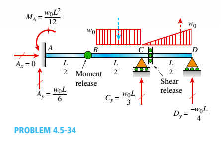
Chapter 4, Problem 4.5.34P
A compound beam (see figure) has an internal moment release just to the left of B and a shear release just to the right of C Reactions have been computed at A, C, and D and are shown in the figure.
First, confirm the reaction expressions using statics; then plot shear (V) and moment (W) diagrams. Label all critical Fand M values and also the distance to points where either V and/or M are zero.
Expert Solution & Answer

Trending nowThis is a popular solution!

Chapter 4 Solutions
Bundle: Mechanics Of Materials, Loose-leaf Version, 9th + Mindtap Engineering, 1 Term (6 Months) Printed Access Card
Ch. 4 - Calculate the shear force V and bending moment...Ch. 4 - Determine the shear force V and bending moment M...Ch. 4 - Determine the shear force V and bending moment M...Ch. 4 - Calculate the shear force V and bending moment M...Ch. 4 - Consider the beam with an overhang shown in the...Ch. 4 - The beam ABC shown in the figure is simply...Ch. 4 - The beam ABCD shown in the figure has overhangs at...Ch. 4 - At a full d raw, an archer applies a pull of 130 N...Ch. 4 - A curved bar ABC is subjected to loads in the form...Ch. 4 - Under cruising conditions, the distributed load...
Ch. 4 - A beam ABCD with a vertical arm CE is supported as...Ch. 4 - A simply supported beam AB supports a trapezoid...Ch. 4 - Beam ABCD represents a reinforced-concrete...Ch. 4 - Find shear (V) and moment (M) at x = 3L/4 for the...Ch. 4 - Find expressions for shear force V and moment M at...Ch. 4 - Find expressions for shear force V and moment Mat...Ch. 4 - Find expressions for shear force V and moment Mat...Ch. 4 - Find expressions for shear force V and moment M at...Ch. 4 - Find expressions for shear force V and moment M at...Ch. 4 - Find expressions for shear force V and moment M at...Ch. 4 - A cable with force P is attached to a frame at A...Ch. 4 - Find expressions for shear force V and moment M at...Ch. 4 - A cable with force P is attached to a frame at D...Ch. 4 - Frame ABCD carries two concentrated loads (2P at T...Ch. 4 - Frame ABC has a moment release just left of joint...Ch. 4 - The simply supported beam ABCD is loaded by a...Ch. 4 - The centrifuge shown in the figure rotates in a...Ch. 4 - Draw the shear-Force and bending-moment diagrams...Ch. 4 - A simple beam AB is subjected to a counter...Ch. 4 - Draw the shear-force and bending-moment diagrams...Ch. 4 - The cantilever beam AB shown in the figure is...Ch. 4 - Cantilever beam AB carries an upward uniform load...Ch. 4 - The simple beam AB shown in the figure is...Ch. 4 - A simple beam AB subjected to couples M1and 3M2...Ch. 4 - A simply supported beam ABC is loaded by a...Ch. 4 - A simply supported beam ABC is loaded at the end...Ch. 4 - A beam ABC is simply supported at A and B and has...Ch. 4 - Beam ABCD is simply supported at B and C and has...Ch. 4 - Draw the shear-force and bending-moment diagrams...Ch. 4 - The simple beam AB supports a triangular load of...Ch. 4 - The beam AB shown in the figure supports a uniform...Ch. 4 - A cantilever beam AB supports a couple and a...Ch. 4 - The cantilever beam A B shown in the figure is...Ch. 4 - Beam ABC has simple supports at .A and B. an...Ch. 4 - Beam ABC with an overhang at one end supports a...Ch. 4 - Consider the two beams shown in the figures. Which...Ch. 4 - The three beams in the figure have the same...Ch. 4 - The beam ABC shown in the figure is simply...Ch. 4 - A simple beam AB is loaded by two segments of...Ch. 4 - Two beams (see figure) are loaded the same and...Ch. 4 - The beam A BCD shown in the figure has overhangs...Ch. 4 - A beam ABCD with a vertical arm CE is supported as...Ch. 4 - Beams ABC and CD are supported at A,C, and D and...Ch. 4 - The simple beam ACE shown in the figure is...Ch. 4 - A beam with simple supports is subjected to a...Ch. 4 - A beam of length L is designed to support a...Ch. 4 - The compound beam ABCDE shown in the figure...Ch. 4 - Draw the shear-force and bending-moment diagrams...Ch. 4 - The shear-force diagram for a simple beam is shown...Ch. 4 - The shear-force diagram for a beam is shown in the...Ch. 4 - A compound beam (see figure) has an internal...Ch. 4 - A compound beam (see figure) has an shear release...Ch. 4 - A simple beam AB supports two connected wheel...Ch. 4 - The inclined beam represents a ladder with the...Ch. 4 - Beam ABC is supported by a tie rod CD as shown....Ch. 4 - A plane frame (see figure) consists of column AB...Ch. 4 - The plane frame shown in the figure is part of an...
Knowledge Booster


Learn more about
Need a deep-dive on the concept behind this application? Look no further. Learn more about this topic, mechanical-engineering and related others by exploring similar questions and additional content below.Similar questions
- Find expressions for shear force V and moment Mat x = 2L/3 of beam (a) in terms of peak load intensity q0 and beam length variable L. Repeat for beam (b).arrow_forwardA fixed-end beam AB of a length L is subjected to a uniform load of intensity q acting over the middle region of the beam (sec figure). Obtain a formula for the fixed-end moments MAand MBin terms of the load q, the length L, and the length h of the loaded part of the beam. Plot a graph of the fixed-end moment MAversus the length b of the loaded part of the beam. For convenience, plot the graph in the following nondimensional form: MAqL2/l2versusbL with the ratio b/L varying between its extreme values of 0 and 1. (c) For the special case in which ù = h = L/3, draw the shear-force and bending-moment diagrams for the beam, labeling all critical ordinates.arrow_forwardFind expressions for shear force V and moment Mat x = 2L/3 of beam (a) in terms of peak load intensity q0and beam length variable L. Repeat for beam (b) but at x = L/2.arrow_forward
- -4-13 A propped cantilever beam of a length 2L is loaded by a uniformly distributed load with intensity q. The beam is supported at B by a linearly elastic spring with stiffness k. Use the method of superposition to solve for all reactions. Also draw shear-force and bending-moment diagrams, labeling all critical ordinates. Let k = 6EI/L3.arrow_forwardFind expressions for shear force V and moment M at mid-span of beam AB in terms of peak load intensity q0and beam length variables a and L Let a = 5L/b.arrow_forwardA counterclockwise moment M0acts at the midpoint of a fixed-end beam ACB of length L (see figure). Beginning with the second-order differential equation of the deflection curve (the bendingmoment equation), determine all reactions of the beam and obtain the equation of the deflection curve for the left-hand half of the beam. Then construct the shear-force and bending-moment diagrams for the entire beam, labeling all critical ordinales. Also, draw the deflection curve for the entire beam.arrow_forward
- A compound beam (see figure) has an shear release just to the left of C and a moment release just to the right of C. A plot of the moment diagram is provided below the beam for applied load P at B and triangular distributed loads v(x) on segments Z/C and CD. First, solve for reactions using statics; then plot axial force (A) and shear force (K) diagrams. Confirm that the moment diagram is that shown below. Label all critical N, V, and M values and also the distance to points where N, V, and/or M are zero.arrow_forwardA beam ABCD with a vertical arm CE is supported as a simple beam at .1 and D (see figure). A cable passes over a small pulley that is attached to the arm at E. One end of the cable is attached to the beam at point B. The tensile force in the cable is 1800 lb. Draw the shear-Force and bending-moment diagrams for beam A BCD. Note: Disregard the widths of the beam and vertical arm and use centerline dimensions when making calculations. Repeat part (a) if a roller support is added at C and a shear release is inserted just left of C (see figure part b).arrow_forwardFind shear (V) and moment (M) at x = 3L/4 for the beam shown in Fig. a. Let MA= 24 kN m,P = 48 kN, L = 6 m, and q0= 8 kN/m. Repeat for the beam in Fig, b (first solve for the reaction moment at fixed support A).arrow_forward
- A fixed-end beam AB of a length L supports a uniform load of intensity q (see figure). Beginning with the second-order differential equation of the deflection curve (the bending-moment equation), obtain the reactions, shear forces, bending moments, slopes, and deflections of the beam. Construct the shear-force and bending-moment diagrams, Labeling all critical ordinales.arrow_forward-1 through 5.10-6 A wide-flange beam (see figure) is subjected to a shear force V. Using the dimensions of the cross section, calculate the moment of inertia and then determine the following quantities: The maximum shear stress tinixin the web. The minimum shear stress rmin in the web. The average shear stress t (obtained by dividing the shear force by the area of the web) and the ratio tmax/taver. The shear force Vweb/V carried in the web and the Vweb/V. Note: Disregard the fillets at the junctions of the web and flanges and determine all quantities, including the moment of inertia, by considering the cross section to consist of three rectangles. 5.10-1 Dimensions of cross section: b = 6 in,, ï = 0.5 in., h = 12 in,, A, = 10.5 in., and V = 30 k.arrow_forwardA beam with a sliding support at B is loaded by a uniformly distributed load with intensity q. Use the method of superposition to solve for all reactions. Also draw shear-force and bending-moment diagrams, labeling all critical ordinales.arrow_forward
arrow_back_ios
SEE MORE QUESTIONS
arrow_forward_ios
Recommended textbooks for you
 Mechanics of Materials (MindTap Course List)Mechanical EngineeringISBN:9781337093347Author:Barry J. Goodno, James M. GerePublisher:Cengage Learning
Mechanics of Materials (MindTap Course List)
Mechanical Engineering
ISBN:9781337093347
Author:Barry J. Goodno, James M. Gere
Publisher:Cengage Learning
Everything About TRANSVERSE SHEAR in 10 Minutes!! - Mechanics of Materials; Author: Less Boring Lectures;https://www.youtube.com/watch?v=4x0E9yvzfCM;License: Standard Youtube License