
SYSTEM DYNAMICS LL+CONNECT
3rd Edition
ISBN: 9781264201891
Author: Palm
Publisher: MCG CUSTOM
expand_more
expand_more
format_list_bulleted
Videos
Textbook Question
Chapter 4, Problem 4.6P
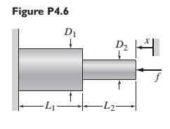
The two stepped solid cylinders in Figure P4.6 consist of the same material and have an axial force f applied to them. Determine the equivalent translational spring constant for this arrangement. (Hint: Are the two springs in series or in parallel?)
Expert Solution & Answer
Want to see the full answer?
Check out a sample textbook solution
Students have asked these similar questions
MECHANICAL VIBRATIONS
The system shown in Fig. P3.3 consists of a uniform rod which has length 1, mass m, and mass moment of inertia about its mass center 1. The rod is supported by two springs which have stiffness coefficients ky and k2, as shown in the figure. Determine the system differential equation of motion for small oscillations. Determine also the system natural frequency.
For each of the systems shown in Figure P4.52, the input is the force f andthe outputs are the displacements x1 and x2 of the masses. The equilibriumpositions with f = 0 correspond to x1 = x2 = 0. Neglect any friction betweenthe masses and the surface. Derive the equations of motion of the systems.
A mass weighing 4 pounds is attached to a spring whose spring constant is 36 lb/ft.
Find the equation of motion.
Chapter 4 Solutions
SYSTEM DYNAMICS LL+CONNECT
Ch. 4 - Prob. 4.1PCh. 4 - In the spring arrangement shown in Figure P4.2....Ch. 4 - In the arrangement shown in Figure P4.3, a cable...Ch. 4 - In the spring arrangement shown in Figure P4.4,...Ch. 4 - For the system shown in Figure P4.5, assume that...Ch. 4 - The two stepped solid cylinders in Figure P4.6...Ch. 4 - A table with four identical legs supports a...Ch. 4 - The beam shown in Figure P4.8 has been stiffened...Ch. 4 - Determine the equivalent spring constant of the...Ch. 4 - Compute the equivalent torsional spring constant...
Ch. 4 - Plot the spring force felt by the mass shown in...Ch. 4 - Calculate the expression for the natural frequency...Ch. 4 - Prob. 4.13PCh. 4 - Obtain the expression for the natural frequency of...Ch. 4 - 4.15 A connecting rod having a mass of 3.6 kg is...Ch. 4 - Calculate the expression for the natural frequency...Ch. 4 - For each of the systems shown in Figure P4.17, the...Ch. 4 - The mass m in Figure P4.18 is attached to a rigid...Ch. 4 - In the pulley system shown in Figure P4.19, the...Ch. 4 - Prob. 4.20PCh. 4 - Prob. 4.21PCh. 4 - Prob. 4.22PCh. 4 - In Figure P4.23, assume that the cylinder rolls...Ch. 4 - In Figure P4.24 when x1=x2=0 the springs are at...Ch. 4 - 4.25 In Figure P4.25 model the three shafts as...Ch. 4 - In Figure P4.26 when 1=2=0 the spring is at its...Ch. 4 - Prob. 4.27PCh. 4 - For the system shown in Figure P4.28, suppose that...Ch. 4 - For the system shown in Figure P4.29, suppose that...Ch. 4 - Prob. 4.30PCh. 4 - For Figure P4.31, the equilibrium position...Ch. 4 - Prob. 4.32PCh. 4 - Prob. 4.33PCh. 4 - 4.34 For Figure P4.34, assume that the cylinder...Ch. 4 - Use the Rayleigh method to obtain an expression...Ch. 4 - Prob. 4.36PCh. 4 - 4.37 Determine the natural frequency of the system...Ch. 4 - Determine the natural frequency of the system...Ch. 4 - Use Rayleigh's method to calculate the expression...Ch. 4 - Prob. 4.40PCh. 4 - Prob. 4.41PCh. 4 - Prob. 4.42PCh. 4 - The vibration of a motor mounted on the end of a...Ch. 4 - Prob. 4.44PCh. 4 - Prob. 4.45PCh. 4 - A certain cantilever beam vibrates at a frequency...Ch. 4 - Prob. 4.47PCh. 4 - 4.48 The static deflection of a cantilever beam is...Ch. 4 - Figure P4.49 shows a winch supported by a...Ch. 4 - Prob. 4.50PCh. 4 - Prob. 4.51PCh. 4 - Prob. 4.52PCh. 4 - 4.53 In Figure P4.53 a motor supplies a torque T...Ch. 4 - Derive the equation of motion for the lever system...Ch. 4 - Prob. 4.55PCh. 4 - Figure P4.56a shows a Houdaille damper, which is a...Ch. 4 - 4.57 Refer to Figure P4.57. Determine the...Ch. 4 - For the system shown in Figure P4.58, obtain the...Ch. 4 - Find the transfer function ZsXs for the system...Ch. 4 - Prob. 4.60PCh. 4 - Find the transfer function YsXs for the system...Ch. 4 - Prob. 4.62PCh. 4 - 4.63 In the system shown in Figure P4.63, the...Ch. 4 - Prob. 4.64PCh. 4 - Figure P4.65 shows a rack-and-pinion gear in which...Ch. 4 - Figure P4.66 shows a drive train with a spur-gear...Ch. 4 - Prob. 4.67PCh. 4 - Prob. 4.68PCh. 4 - Prob. 4.69PCh. 4 - Figure P4.70 shows a quarter-car model that...Ch. 4 - Prob. 4.71PCh. 4 - 4.72 Derive the equation of motion for the system...Ch. 4 - A boxcar moving at 1.3 m/s hits the shock absorber...Ch. 4 - For the systems shown in Figure P4.74, assume that...Ch. 4 - Refer to Figure P4.75a, which shows a ship’s...Ch. 4 - In this problem, we make all the same assumptions...Ch. 4 - Refer to Figure P4.79a, which shows a water tank...Ch. 4 - The “sky crane” shown on the text cover was a...Ch. 4 - Prob. 4.81PCh. 4 - Prob. 4.82PCh. 4 - Suppose a mass in moving with a speed 1 becomes...Ch. 4 - Consider the system shown in Figure 4.6.3. Suppose...Ch. 4 - Prob. 4.86PCh. 4 - Figure P4.87 shows a mass m with an attached...Ch. 4 - Figure P4.88 represents a drop forging process....Ch. 4 - Refer to Figure P4.89. A mass m drops from a...Ch. 4 - Prob. 4.90PCh. 4 - (a) Obtain the equations of motion of the system...Ch. 4 - Refer to part (a) of Problem 4.90. Use MATLAB to...Ch. 4 - Refer to Problem 4.91. Use MATLAB to obtain the...Ch. 4 - 4.94 (a) Obtain the equations of motion of the...Ch. 4 -
4.95 (a) Obtain the equations of motion of the...
Knowledge Booster


Learn more about
Need a deep-dive on the concept behind this application? Look no further. Learn more about this topic, mechanical-engineering and related others by exploring similar questions and additional content below.Similar questions
- 'A model for the elbow joint models the bicep muscle connecting to the horizontal forearm by a vertical tendon 4cm from the elbow joint. A mass m is held in the hand 30cm from the elbow joint. If the maximum tension that can be exerted by the tendon before injury occurs is 2250N, find the maximum mass that can be held in this way.' Im stuck on this questionarrow_forwardIn the mechanical system in the figure, a rigid rod is bedded at point P and has mass m at its end. can rotate vertically. At the other end of the rod, a spring (k) and a damper (c) are attached. Draw the Free-Body Diagram of the system, obtain the Equation of Motion (the vertical position of the ball We assume that the displacement x is very small and the bar is massless).arrow_forwardFigure Q1 shows a uniform plank, rests upon a horizontal bench with one end of the bar projecting over the sharp edge of the bench, the bar being at right angles to this edge. The plank is pulled out of horizontally until the centre of gravity overhangs the edge by a distance a, and is then released. The plank rotates about the edge and then slides down.arrow_forward
- Figure Q3(b) shows a uniform bar AB of mass = 8 kg hinged at point C. Point A is connected to a spring to maintain the bar in vertical direction, and the stiffness k = 500 N/m. If point A is displaced counter-clockwise by a small angle θ = 3.5 degree and released, (i) With the free body diagram and kinetic diagram, determine the initial horizontal displacement of A.arrow_forwardFor the system shown in below figure, determine the equivalent spring constant in the direction of ϴ.arrow_forwardPART OF MECHANICAL VIBRATIONS SUBJECT USE VIRTUAL WORK The uniform bar shown in Fig. P3.6 has mass m, length l, and mass moment of inertia 1 about its mass center. The bar is supported by two springs kı and k2, as shown in the figure. Obtain the differential equation of motion and determine the natural frequency of the system in the case of small oscillations.arrow_forward
- Find the transfer function of the rotational mechanical system shown in the figure, where θ1(t) is the output and T(t) is the input?arrow_forwardTwo masses A and B are 5kg and 2kg respectively rotating in a shaft. The corresponding radii of rotation are 0.2m and 0.3m respectively and the angle between the masses is 600. Find the position and magnitude of the balance mass required, if its radius of rotation is 200 mm using graphical method and also verify your answer with analytical method.arrow_forwardA plate of an unknown weight W is supported by three cables as shown.a) Draw an appropriate FBD and find the unit vectors for each force.b) For TCA = 416 lb, find the magnitudes of each unknown force.*c) What is the maximum weight that can be supported if none of the rope tensions can exceed 1200 lb? Hint: Use the fact that this is a linear system with one input.arrow_forward
- Consider the system formed by three ideal springs, a rigid rod of negligible mass and a body of mass M, as illustrated in the figure. The two springs attached to the ceiling are identical and have spring constant K1 = 2 kg/s2 and natural length L1 = 10 cm, while the third has spring constant K2 = 3 kg/s2 and natural length L2 = 20 cm. Assume that the mass M and the rod oscillate only along the vertical x-axis and that the gravitational acceleration is uniform with magnitude g=10 m/s2. What is the mass oscillation period? Choose the closest value.arrow_forwardFigure Q2 shows two configurations of a part sorting machine in a production process. Since the process involve high speed movement, the design engineer have proposed two configurations of design as shown in Figure Q2 (a) – Configuration 1 and Figure Q2 (b) – Configuration 2. The mass m1 and m2 are 180 kg and 70 kg respectively and the spring coefficient, k = k1 = k2 = k3 = k4 = 300 N/m.(a) Sketch the Free Body Diagram for each configuration (Configuration 1 and Configuration 2).(b)Construct the Equation of Motion for each configuration (Configuration 1 and Configuration 2).(c)Predict which configuration that would lead to the highest first natural frequency, ωn1. State the reason for your answer.(d)Validate your answer in Q2(c) by providing natural frequency ωn calculation for each configuration.arrow_forwardFind the differential equations for the motion of a pendulum in that its mass m is connected to a flexible helical spring (constant of stiffness K and length l. ). Assume that the movement takes place in a vertical plane.arrow_forward
arrow_back_ios
SEE MORE QUESTIONS
arrow_forward_ios
Recommended textbooks for you
 International Edition---engineering Mechanics: St...Mechanical EngineeringISBN:9781305501607Author:Andrew Pytel And Jaan KiusalaasPublisher:CENGAGE L
International Edition---engineering Mechanics: St...
Mechanical Engineering
ISBN:9781305501607
Author:Andrew Pytel And Jaan Kiusalaas
Publisher:CENGAGE L
Mechanical SPRING DESIGN Strategy and Restrictions in Under 15 Minutes!; Author: Less Boring Lectures;https://www.youtube.com/watch?v=dsWQrzfQt3s;License: Standard Youtube License