
SYSTEM DYNAMICS LL+CONNECT
3rd Edition
ISBN: 9781264201891
Author: Palm
Publisher: MCG CUSTOM
expand_more
expand_more
format_list_bulleted
Concept explainers
Videos
Textbook Question
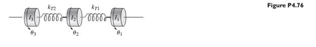
Chapter 4, Problem 4.76P
In this problem, we make all the same assumptions as in Problem 4.75, but we do not discount the flywheel inertia, so our model consists of three inertias, as shown in Figure P4.76. Obtain the natural frequencies of the system.
Expert Solution & Answer
Want to see the full answer?
Check out a sample textbook solution
Students have asked these similar questions
For the following mechanical systems,
obtain the equations of motion in Laplace
domain.
Figure shows a mechanical system. The
connecting link has moment of inertia J about
its pivot point, and rotation angle is positive
clockwise. Position of mass m is positive to
the right. Both the angular and translational
displacements are measured from the
equilibrium position where all springs are
undeflected.
Derive the mathematical model of this system
assuming small rotation angle 8.
Link, moment.
of inertia J
L
k₁
www
m
O
k₂
www
Consider a pulley system shown below. Assume there is no slip between the cord and the pulley. I is the mass moment of inertia of the pulley about its own centroidal axis.
Find the equations of motion in terms of x. Select all that apply.
Chapter 4 Solutions
SYSTEM DYNAMICS LL+CONNECT
Ch. 4 - Prob. 4.1PCh. 4 - In the spring arrangement shown in Figure P4.2....Ch. 4 - In the arrangement shown in Figure P4.3, a cable...Ch. 4 - In the spring arrangement shown in Figure P4.4,...Ch. 4 - For the system shown in Figure P4.5, assume that...Ch. 4 - The two stepped solid cylinders in Figure P4.6...Ch. 4 - A table with four identical legs supports a...Ch. 4 - The beam shown in Figure P4.8 has been stiffened...Ch. 4 - Determine the equivalent spring constant of the...Ch. 4 - Compute the equivalent torsional spring constant...
Ch. 4 - Plot the spring force felt by the mass shown in...Ch. 4 - Calculate the expression for the natural frequency...Ch. 4 - Prob. 4.13PCh. 4 - Obtain the expression for the natural frequency of...Ch. 4 - 4.15 A connecting rod having a mass of 3.6 kg is...Ch. 4 - Calculate the expression for the natural frequency...Ch. 4 - For each of the systems shown in Figure P4.17, the...Ch. 4 - The mass m in Figure P4.18 is attached to a rigid...Ch. 4 - In the pulley system shown in Figure P4.19, the...Ch. 4 - Prob. 4.20PCh. 4 - Prob. 4.21PCh. 4 - Prob. 4.22PCh. 4 - In Figure P4.23, assume that the cylinder rolls...Ch. 4 - In Figure P4.24 when x1=x2=0 the springs are at...Ch. 4 - 4.25 In Figure P4.25 model the three shafts as...Ch. 4 - In Figure P4.26 when 1=2=0 the spring is at its...Ch. 4 - Prob. 4.27PCh. 4 - For the system shown in Figure P4.28, suppose that...Ch. 4 - For the system shown in Figure P4.29, suppose that...Ch. 4 - Prob. 4.30PCh. 4 - For Figure P4.31, the equilibrium position...Ch. 4 - Prob. 4.32PCh. 4 - Prob. 4.33PCh. 4 - 4.34 For Figure P4.34, assume that the cylinder...Ch. 4 - Use the Rayleigh method to obtain an expression...Ch. 4 - Prob. 4.36PCh. 4 - 4.37 Determine the natural frequency of the system...Ch. 4 - Determine the natural frequency of the system...Ch. 4 - Use Rayleigh's method to calculate the expression...Ch. 4 - Prob. 4.40PCh. 4 - Prob. 4.41PCh. 4 - Prob. 4.42PCh. 4 - The vibration of a motor mounted on the end of a...Ch. 4 - Prob. 4.44PCh. 4 - Prob. 4.45PCh. 4 - A certain cantilever beam vibrates at a frequency...Ch. 4 - Prob. 4.47PCh. 4 - 4.48 The static deflection of a cantilever beam is...Ch. 4 - Figure P4.49 shows a winch supported by a...Ch. 4 - Prob. 4.50PCh. 4 - Prob. 4.51PCh. 4 - Prob. 4.52PCh. 4 - 4.53 In Figure P4.53 a motor supplies a torque T...Ch. 4 - Derive the equation of motion for the lever system...Ch. 4 - Prob. 4.55PCh. 4 - Figure P4.56a shows a Houdaille damper, which is a...Ch. 4 - 4.57 Refer to Figure P4.57. Determine the...Ch. 4 - For the system shown in Figure P4.58, obtain the...Ch. 4 - Find the transfer function ZsXs for the system...Ch. 4 - Prob. 4.60PCh. 4 - Find the transfer function YsXs for the system...Ch. 4 - Prob. 4.62PCh. 4 - 4.63 In the system shown in Figure P4.63, the...Ch. 4 - Prob. 4.64PCh. 4 - Figure P4.65 shows a rack-and-pinion gear in which...Ch. 4 - Figure P4.66 shows a drive train with a spur-gear...Ch. 4 - Prob. 4.67PCh. 4 - Prob. 4.68PCh. 4 - Prob. 4.69PCh. 4 - Figure P4.70 shows a quarter-car model that...Ch. 4 - Prob. 4.71PCh. 4 - 4.72 Derive the equation of motion for the system...Ch. 4 - A boxcar moving at 1.3 m/s hits the shock absorber...Ch. 4 - For the systems shown in Figure P4.74, assume that...Ch. 4 - Refer to Figure P4.75a, which shows a ship’s...Ch. 4 - In this problem, we make all the same assumptions...Ch. 4 - Refer to Figure P4.79a, which shows a water tank...Ch. 4 - The “sky crane” shown on the text cover was a...Ch. 4 - Prob. 4.81PCh. 4 - Prob. 4.82PCh. 4 - Suppose a mass in moving with a speed 1 becomes...Ch. 4 - Consider the system shown in Figure 4.6.3. Suppose...Ch. 4 - Prob. 4.86PCh. 4 - Figure P4.87 shows a mass m with an attached...Ch. 4 - Figure P4.88 represents a drop forging process....Ch. 4 - Refer to Figure P4.89. A mass m drops from a...Ch. 4 - Prob. 4.90PCh. 4 - (a) Obtain the equations of motion of the system...Ch. 4 - Refer to part (a) of Problem 4.90. Use MATLAB to...Ch. 4 - Refer to Problem 4.91. Use MATLAB to obtain the...Ch. 4 - 4.94 (a) Obtain the equations of motion of the...Ch. 4 -
4.95 (a) Obtain the equations of motion of the...
Knowledge Booster


Learn more about
Need a deep-dive on the concept behind this application? Look no further. Learn more about this topic, mechanical-engineering and related others by exploring similar questions and additional content below.Similar questions
- Use the energy method to deriving the equations of motion for systems in Fig. 3, 4. Then calculate the resulting displacements due to the application of 1 N force.arrow_forwardIn the system in the figure, the static equilibrium position of the thin, slender homogeneous rod of mass m and length L is horizontal.During the movement of the system, the bar is separated from the horizontal by small angles. (A makes oscillating motion with small angles relative to the simple support point)a) Find the equation of motion of the system in terms of the given parameters.b) Since M=4 kg, m=1 kg, L=1 m, k=600 N/m, c=200 Ns/m, F=300 N, w=4 rad/s, is there resonance in the system? If there is resonance, what would you recommend to get rid of resonance?arrow_forwardFour equal, uniform rods of mass m and length 2a are hinged together to form a rhombus ABCD. The point A is fixed, while C lies directly beneath it and is free to slide up and down. The whole system can rotate around the vertical. Let 0 be the angle that AB makes with the vertical, and o be the angular velocity around the vertical, as shown in figure 3. Find the Lagrangian for this system and show that there are two conserved constants of motion. B Figure 3: The rotating rhombus.arrow_forward
- Question 9: Figure 3 shows a mechanical system. The rod (with moment of inertia J) rotates about the pivot at only small rotation angles. As pictured, theta is positive clockwise. Attached is mass m, which moves positive to the right. When stationary in the position shown, all springs are undeflected. Using BOBODDY, find the mathematical model of this system assuming small rotation angle 0. Link, moment of inertia J k3 L₁ 12 5 Ꮎ wwww Figure 3: Mechanical System m k₂ barrow_forward0.5 m, k = 500 N/m, and k = 40 N.m/rad, In the system shown, m = 10 kg, r = 0.3 m, Ko where ko is the radius of gyration of the pulley about point 0. There is no slippage between the cord and the pulley. Replace the system with an equivalent { a) torsional spring and mass moment of inertia at point 0, and b) translational mass and spring at point A. т, Ко kt А k m wwarrow_forwardQ1: The system shown has two masses. Beam of mass (Jo#m L² kg.m²) rotates about fixed point (O) and its free end is connected to disk rotates about fixed point (O₂). Consider all connecting links are massless and rigid. Find 1- The displacements of points A, B, and C in addition to the rotations of masses, all in terms of 0. 2- Find the equation of motion (EOM) in terms of 0. 3- What is the natural frequency of the system? 0 L/2 8 Energy methods A Jo=m L²2 L/2 Joz-m R² R C B C 128arrow_forward
- The figure below shows a disc, that is in contact with a larger half disc and able to swing on a link arm. Calculate the natural frequency of vibration of the smaller disc (of radius r) rolling back and forth outside the larger disc (of radius R Assume that the outside disc rolls without slipping and has a mass of m 15 kg. the radius of r 0.03 m, and the mass moment of inertia of for about its centre, O Also suppose the mass of the link connecting the centre of the outside disc. O, to the pivot point A is negligible and assume R=2r, where R is the radius of larger half-disc. Take g=9.81 m/s² massless R 105 Hz 063Hz 136 Hz 0.74 Hz 2.35 Hz marrow_forwardDraw a free body diagram and derive the equation of motion of the system below. Find the natural frequency of the given system.arrow_forwardTwo bars, each weighing 5.1 lb/ft, are welded together as shown in figure below. With A = 4.3 ft and B = 6.2 ft, find I, the moment of inertia with respect to the center of the mass in slug-ft2. A В Figure is from "Engineering Mechanic An Introduction to Dynamics", McGill and King.arrow_forward
- TORSIONAL SYSTEM Q-4 For the system in fig (4) find : 1. F.B.D 2. Equation of motion & wd. 3. e(t), for 3 < 1. 4. 8.arrow_forwardA mass weighing 4 pounds is attached to a spring whose spring constant is 36 lb/ft. Find the equation of motion.arrow_forwardFor the system below, the mass, m is attached to the end of a cantilever beam of length, l, elasticity, E, and moment of inertia, I. Derive the equation of motions and find the natural frequencies in two cases by lagrange energy method a) k1=k2=0 b) k1≠k2≠0arrow_forward
arrow_back_ios
SEE MORE QUESTIONS
arrow_forward_ios
Recommended textbooks for you
 International Edition---engineering Mechanics: St...Mechanical EngineeringISBN:9781305501607Author:Andrew Pytel And Jaan KiusalaasPublisher:CENGAGE L
International Edition---engineering Mechanics: St...
Mechanical Engineering
ISBN:9781305501607
Author:Andrew Pytel And Jaan Kiusalaas
Publisher:CENGAGE L
Introduction to Undamped Free Vibration of SDOF (1/2) - Structural Dynamics; Author: structurefree;https://www.youtube.com/watch?v=BkgzEdDlU78;License: Standard Youtube License