
Concept explainers
Videos
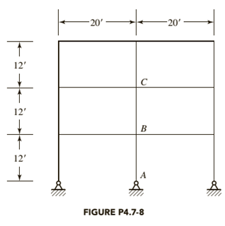
The frame shown in Figure P4.7-8 is unbraced, and bending is about the x-axis of the members. All beams are
a. Determine the effective length factor
b. Determine the effective length factor
c. If

Trending nowThis is a popular solution!

Chapter 4 Solutions
Steel Design (Activate Learning with these NEW titles from Engineering!)


- Question 1) F=20 kN single load, M=23 kN.m moment and w=19 kN/m distributed load are acting on the beam whose loading condition is given in the figure . The length L is also given as L=5 m . The cross-sectional properties of the beam are; body height y g =248 mm , body thickness x g =12 mm , flange width x f = 196 mm , flange height y f = 20 mm . Point E on the section is located just below the flange-body junction. It is desired to determine the stress state in the section taken from the C level of the beam. According to this; Question1-A ) Find the normal force (N C ) at point C. ( Write your result in kN .) Question1-B ) Find the shear force (V C ) at point C. ( Write your result in kN .) Question1-C ) Find the bending moment ( MC) at point C. ( Write your result in kN.m. )arrow_forwardA simply supported beam is loaded as shown. Use E = 200,000MPa and I=150 x 106 mm4. a) Compute for the value of C1 in the equation of the slope for the first segment. b) Compute for the value of C3 (constant of the 1st integration) in the equation of the slope for the 2nd segment.arrow_forward'The I-beam is loaded as shown in the figure. Determine the required flange width b so that the stress caused by bending does not exceed the allowable stress σmax = 170 MPa. The thickness of the flange is tflange= 12 mm, and the thickness of the web inch tweb= 8 mm, so let's look at just bending. F = 48kN, q = 8kN/m, L = 2.2m, H = 500mm Use units [N, mm]. Enter the answer to one decimal place. Do not round the invoices in the intermediate stages, but only the final answer!arrow_forward
- 2.Determine the vertical displacement of joint A (a) if members AB and BC experience a temperature increase of ΔT = 200°F. Take A = 2 in^2 and E = 29(10^3) ksi. Also, a = 6.60 (10^-6)/°F. (b) if member AE is fabricated 0.5 in. too short. Include the effect of external forces in both cases.arrow_forwardA cantilever beam supports the loads shown. The cross-sectional dimensions of the shape are also shown. Assume a = 0.4 m, PA = 2.0 kN, PB = 6.0 kN, PC = 3.0 kN, d = 85 mm, bf = 105 mm, tf = 5 mm, tw = 9 mm. Determine: Calculate the moment of inertia for entire cross-section about its z centroidal axis.Answer: Iz = (106) mm4 Determine the maximum value of Q for the cross-section, where Q is the first moment of the area. Answer: Qmax = (103) mm3 Determine the maximum vertical shear stress.Answer: τmax= MPa At the location of the maximum positive moment, determine the maximum tension bending stress, σT+, and the maximum compression bending stress, σC+. Report the answers here using the correct signs according to the flexure formula (σC+ will be negative). Answers: σT+= MPa σC+ MPa At the location of the maximum negative moment, determine the maximum tension bending…arrow_forwardRigid bar DB in the figure is supported at pin B by axial member ABC, which has a cross-sectional area of A1=A2=65 mm2, an elastic modulus of E1=E2=750 MPa, and lengths of L1=350 mm and L2=640 mm. A load of Q=450 N is applied at end C of member (2), and a load of P=1245 N is applied to the rigid bar at a distance of a=75 mm from pin support D and b=45 mm from pin B. Determine the magnitudes of the downward deflections of: (a) pin B. (b) pin C.arrow_forward
- Determine the vertical displacement of joint A. Each A992 steel member has a cross-sectional area of 400 mm2.arrow_forwardDetermine the slope and the displacement at the end C of the beam. E = 200 GPa, I = 70(106) mm4.arrow_forwardDetermine the displacement at D of the steel beam as shown. Take E = 29(103) ksi, I = 800 in4.arrow_forward
- A rectangular beam has an extended cantilever beam the is attached at the end of the beam. A force P = 165,000 N is acted at the end of cantilever beam. Take S1 = 230 mm, S2 = 300 mm. What is the angle of twist of the beam if the length of the beam is 1500 mm, G = 2.0 MPa. Show complete solution with FBDarrow_forwardA cantilever beam AB with a circular crosssection and length L = 750 mm supports a loadP = 800 N acting at the free end (see figure). Thebeam is made of steel with an allowable bendingstress of 120 MPa.(a) Determine the required diameter dmin (figurepart a) of the beam, considering the effect of thebeam’s own weight.(b) Repeat part (a) if the beam is hollow with wallthickness t =d /8 (figure part b); compare thecross-sectional areas of the two designs.arrow_forwardThe rigid bar BC is supported by the steel rod AC of cross-sectional area 0.27 in2. Find the vertical displacement (in inches and absolute value) of point C caused by the 2448-lb load if x = 9.5 ft and θ = 41.7ᵒ. Use E = 29147 ksi for steel. Note: Round off the final answer to four decimal places.arrow_forward

 Structural Analysis (10th Edition)Civil EngineeringISBN:9780134610672Author:Russell C. HibbelerPublisher:PEARSON
 Principles of Foundation Engineering (MindTap Cou...Civil EngineeringISBN:9781337705028Author:Braja M. Das, Nagaratnam SivakuganPublisher:Cengage Learning
 Fundamentals of Structural AnalysisCivil EngineeringISBN:9780073398006Author:Kenneth M. Leet Emeritus, Chia-Ming Uang, Joel LanningPublisher:McGraw-Hill Education
 Traffic and Highway EngineeringCivil EngineeringISBN:9781305156241Author:Garber, Nicholas J.Publisher:Cengage Learning