
SHIGLEY'S MECHANICAL ENGR DESIGN (LL)
10th Edition
ISBN: 9781308945446
Author: BUDYNAS
Publisher: MCG/CREATE
expand_more
expand_more
format_list_bulleted
Videos
Textbook Question
Chapter 4, Problem 79P
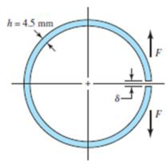
A steel piston ring has a mean diameter of 70 mm. a radial height h = 4.5 mm. and a thickness b = 3 mm. The ring is assembled using an expansion tool that separates the split ends a distance δ by applying a force F as shown. Use Castigliano’s theorem and determine the force F needed to expand the split ends a distance δ = 1 mm.
Problem 4-79
Expert Solution & Answer
Want to see the full answer?
Check out a sample textbook solution
Chapter 4 Solutions
SHIGLEY'S MECHANICAL ENGR DESIGN (LL)
Ch. 4 - The figure shows a torsion bar OA fixed at O,...Ch. 4 - For Prob. 41, if the simple support at point A...Ch. 4 - A torsion-bar spring consists of a prismatic bar,...Ch. 4 - An engineer is forced by geometric considerations...Ch. 4 - A bar in tension has a circular cross section and...Ch. 4 - Prob. 6PCh. 4 - Prob. 7PCh. 4 - Derive the equations given for beam 2 in Table A9...Ch. 4 - Derive the equations given for beam 5 in Table A9...Ch. 4 - The figure shows a cantilever consisting of steel...
Ch. 4 - A simply supported beam loaded by two forces is...Ch. 4 - Using superposition, find the deflection of the...Ch. 4 - A rectangular steel bar supports the two...Ch. 4 - An aluminum tube with outside diameter of 2 in and...Ch. 4 - The cantilever shown in the figure consists of two...Ch. 4 - Using superposition for the bar shown, determine...Ch. 4 - A simply supported beam has a concentrated moment...Ch. 4 - Prob. 18PCh. 4 - Using the results of Prob. 418, use superposition...Ch. 4 - Prob. 20PCh. 4 - Consider the uniformly loaded simply supported...Ch. 4 - Prob. 22PCh. 4 - Prob. 23PCh. 4 - Prob. 24PCh. 4 - Prob. 25PCh. 4 - Prob. 26PCh. 4 - Prob. 27PCh. 4 - Prob. 28PCh. 4 - 429 to 434 For the steel countershaft specified in...Ch. 4 - Prob. 30PCh. 4 - Prob. 31PCh. 4 - Prob. 32PCh. 4 - For the steel countershaft specified in the table,...Ch. 4 - For the steel countershaft specified in the table,...Ch. 4 - Prob. 35PCh. 4 - Prob. 36PCh. 4 - Prob. 37PCh. 4 - Prob. 38PCh. 4 - Prob. 39PCh. 4 - Prob. 40PCh. 4 - The cantilevered handle in the figure is made from...Ch. 4 - Prob. 42PCh. 4 - The cantilevered handle in Prob. 384, p. 154, is...Ch. 4 - A flat-bed trailer is to be designed with a...Ch. 4 - The designer of a shaft usually has a slope...Ch. 4 - Prob. 46PCh. 4 - If the diameter of the steel beam shown is 1.25...Ch. 4 - For the beam of Prob. 4-47, plot the magnitude of...Ch. 4 - Prob. 49PCh. 4 - 4-50 and 4-51 The figure shows a rectangular...Ch. 4 - and 451 the ground at one end and supported by a...Ch. 4 - The figure illustrates a stepped torsion-bar...Ch. 4 - Consider the simply supported beam 5 with a center...Ch. 4 - Prob. 54PCh. 4 - Prob. 55PCh. 4 - Solve Prob. 410 using singularity functions. Use...Ch. 4 - Prob. 57PCh. 4 - Prob. 58PCh. 4 - Prob. 59PCh. 4 - Solve Prob. 413 using singularity functions. Since...Ch. 4 - Prob. 61PCh. 4 - Solve Prob. 419 using singularity functions to...Ch. 4 - Using singularity functions, write the deflection...Ch. 4 - Determine the deflection equation for the...Ch. 4 - Use Castiglianos theorem to verify the maximum...Ch. 4 - Use Castiglianos theorem to verify the maximum...Ch. 4 - Solve Prob. 415 using Castiglianos theorem.Ch. 4 - Solve Prob. 452 using Castiglianos theoremCh. 4 - Determine the deflection at midspan for the beam...Ch. 4 - Using Castiglianos theorem, determine the...Ch. 4 - Solve Prob. 441 using Castiglianos theorem. Since...Ch. 4 - Solve Prob. 442 using Castiglianos theorem.Ch. 4 - The cantilevered handle in Prob. 384 is made from...Ch. 4 - Solve Prob. 450 using Castiglianos theorem.Ch. 4 - Solve Prob. 451 using Castiglianos theorem.Ch. 4 - The steel curved bar shown has a rectangular cross...Ch. 4 - Repeat Prob. 476 to find the vertical deflection...Ch. 4 - For the curved steel beam shown. F = 6.7 kips....Ch. 4 - A steel piston ring has a mean diameter of 70 mm....Ch. 4 - For the steel wire form shown, use Castiglianos...Ch. 4 - 4-81 and 4-82 The part shown is formed from a...Ch. 4 - 4-81 and 4-82 The part shown is formed from a...Ch. 4 - Repeat Prob. 481 for the vertical deflection at...Ch. 4 - Repeat Prob. 482 for the vertical deflection at...Ch. 4 - A hook is formed from a 2-mm-diameter steel wire...Ch. 4 - The figure shows a rectangular member OB, made...Ch. 4 - Prob. 87PCh. 4 - For the wire form shown, determine the deflection...Ch. 4 - Prob. 89PCh. 4 - Prob. 90PCh. 4 - Prob. 91PCh. 4 - Prob. 92PCh. 4 - Solve Prob. 492 using Castiglianos method and...Ch. 4 - An aluminum step bar is loaded as shown. (a)...Ch. 4 - The steel shaft shown in the figure is subjected...Ch. 4 - Repeat Prob. 495 with the diameters of section OA...Ch. 4 - The figure shows a 12- by 1-in rectangular steel...Ch. 4 - For the beam shown, determine the support...Ch. 4 - Solve Prob. 498 using Castiglianos theorem and...Ch. 4 - Consider beam 13 in Table A9, but with flexible...Ch. 4 - Prob. 101PCh. 4 - The steel beam ABCD shown is simply supported at C...Ch. 4 - Prob. 103PCh. 4 - A round tubular column has outside and inside...Ch. 4 - For the conditions of Prob. 4104, show that...Ch. 4 - Link 2, shown in the figure, is 25 mm wide, has...Ch. 4 - Link 3, shown schematically in the figure, acts as...Ch. 4 - The hydraulic cylinder shown in the figure has a...Ch. 4 - The figure shows a schematic drawing of a...Ch. 4 - If drawn, a figure for this problem would resemble...Ch. 4 - Design link CD of the hand-operated toggle press...Ch. 4 - Find the maximum values of the spring force and...Ch. 4 - As shown in the figure, the weight W1 strikes W2...Ch. 4 - Part a of the figure shows a weight W mounted...
Knowledge Booster


Learn more about
Need a deep-dive on the concept behind this application? Look no further. Learn more about this topic, mechanical-engineering and related others by exploring similar questions and additional content below.Similar questions
- The L-shaped arm ABCD shown in the figure lies in a vertical plane and pivots about a horizontal pin at A. The arm has a constant cross-sectional area and total weight W. A vertical spring of stiffness k supports the arm at point B. (a) Obtain a formula for the elongation of the spring due to the weight of the arm. (b) Repeat part (a) if the pin support at A is moved to D.arrow_forwardA thin metal strip of total weight W and length L is placed across the top of a flat table of width L2as shown in the figure. What is the clearance S between the strip and the middle of the table? (The strip of metal has flexural rigidity EI.)arrow_forwardA crane boom of mass 450 leg with its center of mass at C is stabilized by two cables AQ and BQ (Ae= 304 mm2 for each cable) as shown in the figure. A load P = 20 KN is supported at point D. The crane boom lies in the y-z plane. (a) Find the tension forces in each cable: TAQand TBQ(kN}. Neglect the mass of the cables, but include the mass of the boom in addition to load P. (b) Find the average stress (s) in each cable.arrow_forward
- Solve the preceding problem for W = 1.0 lb. h = 12 in.,and k =0.511,/in.arrow_forwardSolve the preceding problem if the collar has mass M = 80 kg, the height h = 0.5 m, the length L = 3.0 m, the cross-sectional area A = 350mm2. and the modulus of elasticity E = 170 GPa.arrow_forwardA T-frame structure is torn posed of a prismatic beam ABC and a nonprismatic column DBF. The beam and the column have a pin support at .A and D, respectively. Both members are connected with a pin at B. The lengths and properties of the members are shown in the figure. Find the vertical displacement of the column at points F and B. Plot axial force (AFD) and axial displacement (ADD) diagrams For column DBF.arrow_forward
- A horizontal bracket ABC consists of two perpendicular arms AB of a length 0.75 m and BC of a length 0,5 m. The bracket has a solid, circular cross section with a diameter equal to 65 mm. The bracket is inserted in a friction less sleeve at A (which is slightly larger in diameter), so it is free to rotate about the r0 axis at A and is supported by a pin at C Moments are applied at point C M{=1.5 kN -m in the x direction and A/3 = L0 kN-m acts in the — z direction. Considering only the moments Mxand M2, calculate the maximum tensile stress t, the maximum compressive stress crc* and the maximum in-plane shear stress Tmax at point />, which is located at support A on the side of the bracket at mid-heightarrow_forwardA shock mount constructed as shown iu the figure is used to support a delicate instrument. The mount consists of an outer steel tube with inside diameter b. a central steel bar of diameter d that supports the load P, and a hollow rubber cylinder (height /r) bonded to the tube and bar (a) Obtain a formula Tor the shear stress t in the rubber at a radial distance r from the center of the shock mount. (b) Obtain a formula Tor the downward displacement S of the central bar due to the load P. assuming that G is the shear modulus of elasticity of the rubber and that the steel tube and bar are rigid.arrow_forwardCompare the angle of twist 1 for a thin-walled circular tube (see figure) calculated from the approximate theory for thin-walled bars with the angle of twist 2 calculated from the exact theory of torsion for circular bars, Express the ratio 12terms of the non-dimensional ratio ß = r/t. Calculate the ratio of angles of twist for ß = 5, 10, and 20. What conclusion about the accuracy of the approximate theory do you draw from these results?arrow_forward
- -19 The mechanical assembly shown in the figure consists of an aluminum tube, a rigid end plate, and two steel cables. The slack is removed from the cables by rotating the turnbuckles until the assembly is snug but with no initial stresses. Afterward, the turnbuckles are tightened by 1.5 turns. Calculate the forces in the tube and the cables and determine the shortening of the tube. As= 0.85 in2 for each cable, AA= 4.5 in2, L = 20 in., Es= 29,000 ksi, EA= 10,600 ksi, and p = 1/16 inarrow_forwardThe Force in the brake cable of the V-brake system shown in the figure is T — 45 lb. The pivot pin at A has a diameter d. = 0.25 in. and length L„ = 5/S in. Use the dimensions shown in the figure. Neglect the weight of the brake system. (a) Find the average shear stress rjm in the pivot pin where it is anchored to the bicycle frame at B. (b) Find the average bearing stress raverin the pivot pin over segment AB. (a) Find support reactions at A and B. (b) Find the resultant force in the shoe boll at A. (c) Find maximum average shear T and bearing AB stresses in the shoe bolt at A.arrow_forwardA mountain bike is moving along a flat path at constant velocity. At some instant, the rider (weight = 670 N) applies pedal and hand forces, as shown in the figure part a. (a) Find reaction forces at the front and rear hubs. (Assume that the bike is pin supported at the rear hub and roller supported at the front hub.) (b) Find internal stress resultants N, V, and M in the inclined seat post (see figure part barrow_forward
arrow_back_ios
SEE MORE QUESTIONS
arrow_forward_ios
Recommended textbooks for you
 Mechanics of Materials (MindTap Course List)Mechanical EngineeringISBN:9781337093347Author:Barry J. Goodno, James M. GerePublisher:Cengage Learning
Mechanics of Materials (MindTap Course List)
Mechanical Engineering
ISBN:9781337093347
Author:Barry J. Goodno, James M. Gere
Publisher:Cengage Learning
Mechanical SPRING DESIGN Strategy and Restrictions in Under 15 Minutes!; Author: Less Boring Lectures;https://www.youtube.com/watch?v=dsWQrzfQt3s;License: Standard Youtube License