
SHIGLEY'S MECHANICAL ENGR DESIGN (LL)
10th Edition
ISBN: 9781308945446
Author: BUDYNAS
Publisher: MCG/CREATE
expand_more
expand_more
format_list_bulleted
Concept explainers
Videos
Textbook Question
Chapter 4, Problem 111P
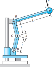
Design link CD of the hand-operated toggle press shown in the figure. Specify the cross-section dimensions, the bearing size and rod-end dimensions, the material, and the method of processing.
Problem 4–111
L = 9 in, l = 3 in, θmin = 0°.
Expert Solution & Answer
Want to see the full answer?
Check out a sample textbook solution
Chapter 4 Solutions
SHIGLEY'S MECHANICAL ENGR DESIGN (LL)
Ch. 4 - The figure shows a torsion bar OA fixed at O,...Ch. 4 - For Prob. 41, if the simple support at point A...Ch. 4 - A torsion-bar spring consists of a prismatic bar,...Ch. 4 - An engineer is forced by geometric considerations...Ch. 4 - A bar in tension has a circular cross section and...Ch. 4 - Prob. 6PCh. 4 - Prob. 7PCh. 4 - Derive the equations given for beam 2 in Table A9...Ch. 4 - Derive the equations given for beam 5 in Table A9...Ch. 4 - The figure shows a cantilever consisting of steel...
Ch. 4 - A simply supported beam loaded by two forces is...Ch. 4 - Using superposition, find the deflection of the...Ch. 4 - A rectangular steel bar supports the two...Ch. 4 - An aluminum tube with outside diameter of 2 in and...Ch. 4 - The cantilever shown in the figure consists of two...Ch. 4 - Using superposition for the bar shown, determine...Ch. 4 - A simply supported beam has a concentrated moment...Ch. 4 - Prob. 18PCh. 4 - Using the results of Prob. 418, use superposition...Ch. 4 - Prob. 20PCh. 4 - Consider the uniformly loaded simply supported...Ch. 4 - Prob. 22PCh. 4 - Prob. 23PCh. 4 - Prob. 24PCh. 4 - Prob. 25PCh. 4 - Prob. 26PCh. 4 - Prob. 27PCh. 4 - Prob. 28PCh. 4 - 429 to 434 For the steel countershaft specified in...Ch. 4 - Prob. 30PCh. 4 - Prob. 31PCh. 4 - Prob. 32PCh. 4 - For the steel countershaft specified in the table,...Ch. 4 - For the steel countershaft specified in the table,...Ch. 4 - Prob. 35PCh. 4 - Prob. 36PCh. 4 - Prob. 37PCh. 4 - Prob. 38PCh. 4 - Prob. 39PCh. 4 - Prob. 40PCh. 4 - The cantilevered handle in the figure is made from...Ch. 4 - Prob. 42PCh. 4 - The cantilevered handle in Prob. 384, p. 154, is...Ch. 4 - A flat-bed trailer is to be designed with a...Ch. 4 - The designer of a shaft usually has a slope...Ch. 4 - Prob. 46PCh. 4 - If the diameter of the steel beam shown is 1.25...Ch. 4 - For the beam of Prob. 4-47, plot the magnitude of...Ch. 4 - Prob. 49PCh. 4 - 4-50 and 4-51 The figure shows a rectangular...Ch. 4 - and 451 the ground at one end and supported by a...Ch. 4 - The figure illustrates a stepped torsion-bar...Ch. 4 - Consider the simply supported beam 5 with a center...Ch. 4 - Prob. 54PCh. 4 - Prob. 55PCh. 4 - Solve Prob. 410 using singularity functions. Use...Ch. 4 - Prob. 57PCh. 4 - Prob. 58PCh. 4 - Prob. 59PCh. 4 - Solve Prob. 413 using singularity functions. Since...Ch. 4 - Prob. 61PCh. 4 - Solve Prob. 419 using singularity functions to...Ch. 4 - Using singularity functions, write the deflection...Ch. 4 - Determine the deflection equation for the...Ch. 4 - Use Castiglianos theorem to verify the maximum...Ch. 4 - Use Castiglianos theorem to verify the maximum...Ch. 4 - Solve Prob. 415 using Castiglianos theorem.Ch. 4 - Solve Prob. 452 using Castiglianos theoremCh. 4 - Determine the deflection at midspan for the beam...Ch. 4 - Using Castiglianos theorem, determine the...Ch. 4 - Solve Prob. 441 using Castiglianos theorem. Since...Ch. 4 - Solve Prob. 442 using Castiglianos theorem.Ch. 4 - The cantilevered handle in Prob. 384 is made from...Ch. 4 - Solve Prob. 450 using Castiglianos theorem.Ch. 4 - Solve Prob. 451 using Castiglianos theorem.Ch. 4 - The steel curved bar shown has a rectangular cross...Ch. 4 - Repeat Prob. 476 to find the vertical deflection...Ch. 4 - For the curved steel beam shown. F = 6.7 kips....Ch. 4 - A steel piston ring has a mean diameter of 70 mm....Ch. 4 - For the steel wire form shown, use Castiglianos...Ch. 4 - 4-81 and 4-82 The part shown is formed from a...Ch. 4 - 4-81 and 4-82 The part shown is formed from a...Ch. 4 - Repeat Prob. 481 for the vertical deflection at...Ch. 4 - Repeat Prob. 482 for the vertical deflection at...Ch. 4 - A hook is formed from a 2-mm-diameter steel wire...Ch. 4 - The figure shows a rectangular member OB, made...Ch. 4 - Prob. 87PCh. 4 - For the wire form shown, determine the deflection...Ch. 4 - Prob. 89PCh. 4 - Prob. 90PCh. 4 - Prob. 91PCh. 4 - Prob. 92PCh. 4 - Solve Prob. 492 using Castiglianos method and...Ch. 4 - An aluminum step bar is loaded as shown. (a)...Ch. 4 - The steel shaft shown in the figure is subjected...Ch. 4 - Repeat Prob. 495 with the diameters of section OA...Ch. 4 - The figure shows a 12- by 1-in rectangular steel...Ch. 4 - For the beam shown, determine the support...Ch. 4 - Solve Prob. 498 using Castiglianos theorem and...Ch. 4 - Consider beam 13 in Table A9, but with flexible...Ch. 4 - Prob. 101PCh. 4 - The steel beam ABCD shown is simply supported at C...Ch. 4 - Prob. 103PCh. 4 - A round tubular column has outside and inside...Ch. 4 - For the conditions of Prob. 4104, show that...Ch. 4 - Link 2, shown in the figure, is 25 mm wide, has...Ch. 4 - Link 3, shown schematically in the figure, acts as...Ch. 4 - The hydraulic cylinder shown in the figure has a...Ch. 4 - The figure shows a schematic drawing of a...Ch. 4 - If drawn, a figure for this problem would resemble...Ch. 4 - Design link CD of the hand-operated toggle press...Ch. 4 - Find the maximum values of the spring force and...Ch. 4 - As shown in the figure, the weight W1 strikes W2...Ch. 4 - Part a of the figure shows a weight W mounted...
Knowledge Booster


Learn more about
Need a deep-dive on the concept behind this application? Look no further. Learn more about this topic, mechanical-engineering and related others by exploring similar questions and additional content below.Similar questions
- Repeat Problem 2.3-4, but now include the weight of the bar. Sec Table 1.1 in Appendix I for the weight density of steel.arrow_forwardA solid circulai' aluminum bar AB is fixed at both ends and loaded by a uniformly distributed torque 150N·n/m. The bar has diameter d = 30 mm. Calculate the reactive torques at the supports and the angle of twist at midspan. Assume that G = 28 GPa.arrow_forwardA crank arm consists of a solid segment of length bxand diameter rf, a segment of length bltand a segment of length byas shown in the figure. Two loads P act as shown: one parallel to — vand another parallel to —y. Each load P equals 1.2 kN. The crankshaft dimensions are A] = 75 mm, fr> = 125 mm, and b3= 35 mm. The diameter of the upper shaft isd = 22 mm, (a) Determine the maximum tensile, compressive, and shear stresses at point A, which is located on the surface of the shaft at the z axis. (b) Determine the maximum tensile, compressive, and shear stresses at point B, which is located on the surface of the shaft at the y axisarrow_forward
- Solve the preceding problem for a W 250 × 44.8 wide-flange shape with L = 3.5 m. q = 45 kN/m, h = 267 mm, b = 148 mm, rt = 13 mm, = 7.62 mm, d = 0.5 m, and a = 50 mm.arrow_forwardA magnesium-alloy wire of diameter d = 4mm and length L rotates inside a flexible tube in order to open or close a switch from a remote location (see figure). A torque Tis applied manually (either clockwise or counterclockwise) at end 5, thus twisting the wire inside the tube. At the other end A, the rotation of the wire operates a handle that opens or closes the switch. A torque T0 = 0.2 N · m is required to operate the switch. The torsional stiffness of the tube, combined with friction between the tube and the wire, induces a distributed torque of constant intensity t = 0.04N m/m (torque per unit distance) acting along the entire length of the wire. (a) If the allowable shear stress in the wire is T allow = 30 MPa, what is the longest permissible length Lmaxof the wire?arrow_forwardRepeat Problem 10.3-15 using L = 3.5 m, max = 3 mm, and EI = 800 kN·m2.arrow_forward
- What is the maximum possible value of the clamping Force C in the jaws of the pliers shown in the figure if the ultimate shear stress in the 5-mm diameter pin is 340 MPa? What is the maximum permissible value of the applied load P to maintain a factor of safety of 3.0 with respect to failure of the pin?arrow_forwardRepeat Problem 11.3-9. Use two C 150 × 12.2 steel shapes and assume that E = 205 GPa and L = 6 m.arrow_forwardRepeat Problem 11.2-3 assuming that R= 10 kN · m/rad and L = 2 m.arrow_forward
- A hollow circular tube A fits over the end of a solid circular bar B, as shown in the figure. The far ends of both bars are fixed. Initially, a hole through bar B makes an angle ß with a line through two holes in tube A. Then bar B is twisted until the holes are aligned, and a pin is placed through the holes. When bar B is released and the system returns to equilibrium, what is the total strain energy U of the two bars? (Let lAand lBrepresent the polar moments of inertia of bars A and B, respectively. The length L and shear modulus of elasticity G are the same for both bars.)arrow_forwardThe piston in an engine is attached to a connecting rod AB, which in turn is connected to a crank arm BC (see figure). The piston slides without friction in a cylinder and is subjected to a force P (assumed to be constant) while moving to the right in the Figure. The connecting rod. with diameter d and length L, is attached at both ends by pins. The crank arm rotates about the axle at C with the pin at B moving in a circle of radius R. The axle at C, which is supported by bearings, exerts a resisting moment M against the crank arm. (a) Obtain a formula for the maximum permissible force Pallow. based upon an allowable compressive stress acin the connecting rod. (b) Calculate the Force Pallowfor the following data:arrow_forwardA statically indeterminate stepped shaft ACE is fixed at ends A and B and loaded by a torque TQat point C (see figure). The two segments of the bar are made of the same material, have lengths L4and LB, and have polar moments of inertia IAand Ipb. Determine the angle of rotation 4>of the cross section at Cby using strain energy. Hint: Use Eq, (3-55b) to determine the strain energy Urn terms of the angle d?. Then equate the strain energy to the work done by the torque to. Compare your result with Eq. (3-52) of Example 3-9.arrow_forward
arrow_back_ios
SEE MORE QUESTIONS
arrow_forward_ios
Recommended textbooks for you
 Mechanics of Materials (MindTap Course List)Mechanical EngineeringISBN:9781337093347Author:Barry J. Goodno, James M. GerePublisher:Cengage Learning
Mechanics of Materials (MindTap Course List)
Mechanical Engineering
ISBN:9781337093347
Author:Barry J. Goodno, James M. Gere
Publisher:Cengage Learning
Understanding Torsion; Author: The Efficient Engineer;https://www.youtube.com/watch?v=1YTKedLQOa0;License: Standard YouTube License, CC-BY