
Concept explainers
Videos
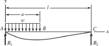
Consider the uniformly loaded simply supported steel beam with an overhang as shown. The second-area moment of the beam is I = 0.05 in4. Use superposition (with Table A–9 and the results of Prob. 4–20) to determine the reactions and the deflection equations of the beam. Plot the deflections.
Problem 4–21
The net reaction at
The net reaction at
The expression for the deflection in the beam of portion
The expression for the deflection in the beam of portion
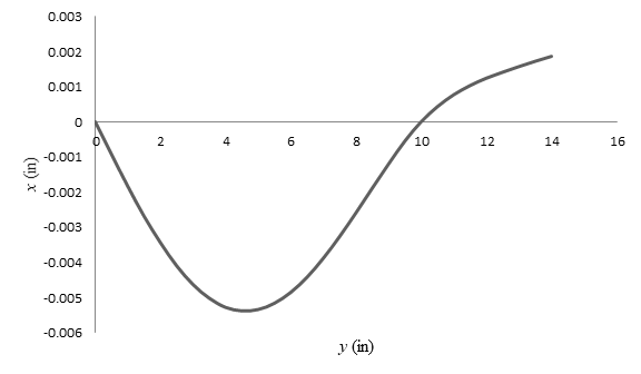
The plot of deflection verses length of the beam.
Answer to Problem 21P
The net reaction at
The net reaction at
The expression for the deflection in the beam of portion
The expression for the deflection in the beam of portion
The plot of deflection verses length of the beam is
Explanation of Solution
Write the expression for the reaction at
Here, the uniform load on the beam is
Write the expression for the reaction at
Here, the reaction at the
Write the expression for the deflection of the beam between
Here, the moment of inertia of the beam is
Write the expression for the slope of the deflection in the beam.
Substitute
Substitute
Write the expression for the deflection of the beam for
Substitute
Write the expression for the reaction at one end of the overhang section.
Here, the distance between
Write the expression for the reaction at other end of the overhang section.
Write the expression for the deflection in the beam section
Write the expression for the deflection in the beam section
Write the expression for the net reaction at
Write the expression for the net reaction at
Add equation (III) and (XI).
Add equation (VII) and (XII).
Conclusion:
Substitute
Substitute
Substitute
Substitute
Substitute
Thus, the net reaction at
Substitute
Thus, the net reaction at
Substitute
Thus, the expression for the deflection in the beam of portion
Substitute
Thus, the expression for the deflection in the beam of portion
Substitute different values of
Substitute
Substitute
Similarly,
Use excel spread sheet to calculate the
The Table-(1) shows the different values of the deflection at different point of the beam.
Table-(1)
| S. No. | length | deflection |
| 1 | ||
| 2 | ||
| 3 | ||
| 4 | ||
| 5 | ||
| 6 | ||
| 7 | ||
| 8 | ||
| 9 | ||
| 10 | ||
| 11 | ||
| 12 | ||
| 13 | ||
| 14 | ||
| 15 | ||
| 16 | ||
| 17 | ||
| 18 | ||
| 19 | ||
| 20 | ||
| 21 | ||
| 22 | ||
| 23 | ||
| 24 | ||
| 25 | ||
| 26 | ||
| 27 | ||
| 28 | ||
| 29 |
Draw the plot of length of the beam verses deflection of the beam.
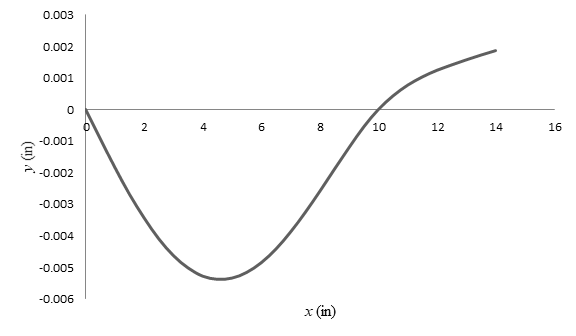
Figure-(1)
Want to see more full solutions like this?
Chapter 4 Solutions
SHIGLEY'S MECHANICAL ENGR DESIGN (LL)


- -18 The beam shown in the figure has a sliding support at A and a spring support at B, The sliding support permits vertical movement but no rotation. Derive the equation of the deflection curve and determine the deflection Bat end B due to the uniform load of intensity q. Use the second-order differential equation of the deflection curve.arrow_forwardThe column shown in the figure is fixed at the base and free at the upper end. A compressive load P acts at the top of the column with an eccentricity e from the axis of the column. Beginning with the differential equation of the deflection curve, derive formulas for the maximum deflection S of the column and the maximum bending moment Mmaxin the column.arrow_forwardA cantilever beam is subjected to a concentrated moment at B, The length of the beam L = 3 m and the height h = 600 mm. The longitudinal strain at the top of the beam is 0,0005 and the distance from the neutral surface to the bottom surface of the Iva m is 300 nun. Find the radius of curvature, the curvature, and the deflection of the beam at B.arrow_forward
- The beam AB shown in the figure supports a uniform load of intensity 3000 N/m acting over half the length of the beam. The beam rests on a foundation that produces a uniformly distributed load over the entire length. Draw the shear-force and bending-moment diagrams for this beam. Repeat part (a) for the distributed load variation shown in Fig. b.arrow_forwardThe cantilever beam AB shown in the figure has an extension BCD attached to its free end. A force P acts at the end of the extension. Find the ratio aiL so that the vertical deflection of point B will be zero. Find the ratio aiL so that the angle of rotation at point B will be zero.arrow_forwardA fixed-end beam is loaded by a uniform load q = 15 kN/m and a point load P = 30 kN at mid-span. The beam has a length of 4 m and modulus of elasticity of 205 GPa. Find reactions at A and B. Calculate the height of the beam if the displacement at mid-span is known to be 3 mm. Assume that the beam has rectangular cross section with h/b = 2.arrow_forward
- A cable CD of a length H is attached to the third point of a simple beam AB of a length L (see figure). The moment of inertia of the beam is I, and the effective cross-sectional area of the cable is A. The cable is initially taut but without any initial tension, (a) Obtain a formula for the tensile force S in the cable when the temperature drops uniformly by T degrees, assuming that the beam and cable are made of the same material (modulus of elasticity E and coefficient of thermal expansion . Use the method of superposition in the solution, (b) Repeat part (a), assuming a wood beam and steel cable.arrow_forward-4-4 A cantilever beam is supported at B by cable BC. The beam carries a uniform load q = 200 N/M. If the length of the beam is L = 3 m, find the force in the cable and the reactions at A. Ignore the axial flexibility of the cable.arrow_forwardA horizontal load P acts at end C of the bracket ABC shown in the figure. Determine the deflection 6Cof point C. Determine the maximum upward deflection 8 of member AB. Note: Assume that the flexural rigidity EI is constant throughout the frame. Also, disregard the effects of axial deformations and consider only the effects of bending due to the load P.arrow_forward
- -9 Derive the equations of the deflection curve for beam ABC with sliding support at A and roller support at B, supporting a uniform load of intensity q acting on the overhang portion of the beam (see figure). Also, determine deflection cand angle of rotation c. Use the fourth-order differential equation of the deflection curve (the load equation).arrow_forward-3 The simple beam AB shown in the figure has moments 2M0and A/0 acting at the ends. Derive the equation of the deflection curve, and then determine the maximum deflection max Use the third-order differential equation of the deflection curve (the shear-force equation).arrow_forward-6 Calculate the maximum deflection of a uniformly loaded simple beam if the span length L = 2.0 m, the intensity of the uniform load q = 2.0 kN/m, and the maximum bending stress = 60 MPa, The cross section of the beam is square, and the material is aluminum having modulus of elasticity E = 70 GPa. (Use the formulas of Example 9-1.)arrow_forward
 Mechanics of Materials (MindTap Course List)Mechanical EngineeringISBN:9781337093347Author:Barry J. Goodno, James M. GerePublisher:Cengage Learning