Vector Mechanics for Engineers: Statics, 11th Edition
11th Edition
ISBN: 9780077687304
Author: Ferdinand P. Beer, E. Russell Johnston Jr., David Mazurek
Publisher: McGraw-Hill Education
Question
Book Icon
Chapter 4.1, Problem 4.27P

(a)

To determine

Find the reactions at A and B when α=0.

(a)

Expert Solution
Check Mark

Answer to Problem 4.27P

The reaction at A is 37.5lb_.

The reaction at B is 37.5lb_.

Explanation of Solution

Given information:

The value of angle is α=0.

Assumption:

Apply the sign convention for calculating the equations of equilibrium as below:

  • For the horizontal forces equilibrium condition, take the force acting towards right side as positive (+) and the force acting towards left side as negative ().
  • For the vertical forces equilibrium condition, take the upward force as positive (+) and downward force as negative ().
  • For moment equilibrium condition, take the clockwise moment as negative and counter clockwise moment as positive.

Calculation:

Consider the condition α=0°.

Draw the free body diagram when α=0° at B. At an angle α=0°, the vertical force only acting at B.

Sketch the Free Body Diagram as shown in Figure 1.
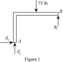
Vector Mechanics for Engineers: Statics, 11th Edition, Chapter 4.1, Problem 4.27P , additional homework tip  1

Refer to Figure 1.

Apply the Equations of Equilibrium as shown below.

Apply the Equilibrium of moment about A is Equal to zero.

MA=0By×2075×10=020By=750By=37.5lb

Hence, the reaction at B is 37.5lb_.

Apply the Equilibrium of forces along x direction as shown below.

Fx=0Ax=0

Apply the Equilibrium of forces along y direction as shown below.

Fy=0Ay75+37.5=0Ay=37.5lb

Hence, the reaction at A is 37.5lb_.

(b)

To determine

The reactions at A and B when α=90°.

(b)

Expert Solution
Check Mark

Answer to Problem 4.27P

The reaction at A is 97.6lb50.2°_.

The reaction at B is 62.5lb_.

Explanation of Solution

Given information:

The angle is α=90°.

Calculation:

Consider the condition α=90°.

Draw the free body diagram when α=90° at B. At an angle α=90°, the horizontal force only acting at B.

Sketch the Free Body Diagram as shown in Figure 2.
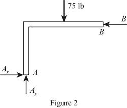
Vector Mechanics for Engineers: Statics, 11th Edition, Chapter 4.1, Problem 4.27P , additional homework tip  2

Refer to Figure 2.

Apply the Equations of Equilibrium as shown below.

Apply the Equilibrium of moment about A is Equal to zero.

MA=0Bx×1275×10=012Bx=750Bx=62.5lb

Hence, the reaction at B is 62.5lb_.

Apply the Equilibrium of forces along x direction as shown below.

Fx=0AxBx=0

Substitute 62.5lb for Bx.

Ax=62.5lb

Apply the Equilibrium of forces along y direction as shown below.

Fy=0Ay75=0Ay=75lb

Calculate the resultant reaction at A as shown below.

A=Ax2+Ay2

Substitute 62.5lb for Ax and 75lb for Ay.

A=62.52+752=9,531.25=97.6lb

Calculate the angle (θ) as shown below.

tanθ=AyAx

Substitute 62.5lb for Ax and 75lb for Ay.

tanθ=7562.5θ=tan1(1.2)θ=50.2°

Hence, the reaction at A is 97.6lb50.2°_.

(c)

To determine

The reactions at A and B when α=30°.

(c)

Expert Solution
Check Mark

Answer to Problem 4.27P

The reaction at A is 49.8lb71.2°_.

The reaction at B is 32.2lb60°_.

Explanation of Solution

Given information:

The angle is α=30°.

Calculation:

Consider the condition α=30°.

Draw the free body diagram when α=30° at B.

Sketch the Free Body Diagram as shown in Figure 3.
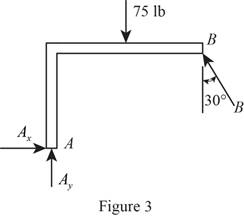
Vector Mechanics for Engineers: Statics, 11th Edition, Chapter 4.1, Problem 4.27P , additional homework tip  3

Refer to Figure 3.

Apply the Equations of Equilibrium as shown below.

Apply the Equilibrium of moment about A is Equal to zero.

MA=0(Bcos30°×20)+(Bsin30°×12)(75×10)=023.32B=750B=32.16lb

Hence, the reaction at B is 32.16lb60°_.

Apply the Equilibrium of forces along x direction as shown below.

Fx=0AxBsin30°=0

Substitute 32.16lb for B.

Ax32.16sin30°=0Ax=16.08lb

Apply the Equilibrium of forces along y direction as shown below.

Fy=0Ay75+32.16cos30°=0Ay=47.149lb

Calculate the resultant reaction at A as shown below.

A=Ax2+Ay2

Substitute 16.08lb for Ax and 47.149lb for Ay.

A=16.082+47.1492=2,481.5946=49.8lb

Calculate the angle (α) as shown below.

tanα=AyAx

Substitute 16.08lb for Ax and 47.149lb for Ay.

tanα=47.14916.08α=tan1(2.93215)α=71.2°

Therefore, the reaction at A is 49.8lb71.2°_.

Want to see more full solutions like this?

Subscribe now to access step-by-step solutions to millions of textbook problems written by subject matter experts!

Chapter 4 Solutions

Vector Mechanics for Engineers: Statics, 11th Edition

Ch. 4.1 - 4.7 A T-shaped bracket supports the four loads...Ch. 4.1 - 4.8 For the bracket and loading of Prob. 4.7,...Ch. 4.1 - Three loads are applied as shown to a light beam...Ch. 4.1 - 4.10 Three loads are applied as shown to a light...Ch. 4.1 - 4.11 For the beam of Prob. 4.10, determine the...Ch. 4.1 - For the beam of Sample Prob. 4.2, determine the...Ch. 4.1 - The maximum allowable value of each of the...Ch. 4.1 - For the beam and loading shown, determine the...Ch. 4.1 - Prob. 4.15PCh. 4.1 - Prob. 4.16PCh. 4.1 - Prob. 4.17PCh. 4.1 - Prob. 4.18PCh. 4.1 - The bracket BCD is hinged at C and attached to a...Ch. 4.1 - The ladder AB, of length L and weight W, can be...Ch. 4.1 - 4.21 The 40-ft boom AB weighs 2 kips; the distance...Ch. 4.1 - A lever AB is hinged at C and attached to a...Ch. 4.1 - 4.23 and 4.24 For each of the plates and loadings...Ch. 4.1 - 4.23 and 4.24 For each of the plates and loadings...Ch. 4.1 - A rod AB, hinged at A and attached at B to cable...Ch. 4.1 - Fig. P4.25 and P4.26 4.26 A rod AB, hinged at A...Ch. 4.1 - Prob. 4.27PCh. 4.1 - Determine the reactions at A and C when (a) = 0,...Ch. 4.1 - Prob. 4.29PCh. 4.1 - Prob. 4.30PCh. 4.1 - Neglecting friction, determine the tension in...Ch. 4.1 - Fig. P4.31 and P4.32 4.32 Neglecting friction,...Ch. 4.1 - PROBLEM 4.33 A force P of magnitude 90 lb is...Ch. 4.1 - PROBLEM 4.34 Solve Problem 4,33 for a = 6 in,...Ch. 4.1 - Bar AC supports two 400-N loads as shown. Rollers...Ch. 4.1 - PROBLEM 4.36 A light bar AD is suspended from a...Ch. 4.1 - Prob. 4.37PCh. 4.1 - Prob. 4.38PCh. 4.1 - Prob. 4.39PCh. 4.1 - 4.40 A light bar AB supports a 15-kg block at its...Ch. 4.1 - 4.41 Two slots have been cut in plate DEF, and the...Ch. 4.1 - Prob. 4.42PCh. 4.1 - The rig shown consists of a 1200-lb horizontal...Ch. 4.1 - Fig. P4.43 4.44 For the rig and crate of Prob....Ch. 4.1 - A 175-kg utility pole is used to support at C the...Ch. 4.1 - Knowing that the tension in wire BD is 1300 N,...Ch. 4.1 - Fig. P4.46 and P4.47 4.47 Determine the range of...Ch. 4.1 - Beam AD carries the two 40-lb loads shown. The...Ch. 4.1 - Fig. P4.48 and P4.49 4.49 For the beam and loading...Ch. 4.1 - Prob. 4.50PCh. 4.1 - A uniform rod AB with a length of l and weight of...Ch. 4.1 - Rod AD is acted upon by a vertical force P at end...Ch. 4.1 - A slender rod AB with a weigh of W is attached to...Ch. 4.1 - 4.54 and 4.55 A vertical load P is applied at end...Ch. 4.1 - 4.54 and 4.55 A vertical load P is applied at end...Ch. 4.1 - A collar B with a weight of W can move freely...Ch. 4.1 - A 400-lb weight is attached at A to the lever...Ch. 4.1 - Prob. 4.58PCh. 4.1 - Eight identical 500 750-mm rectangular plates,...Ch. 4.1 - Prob. 4.60PCh. 4.2 - A 500-lb cylindrical tank, 8 ft in diameter, is to...Ch. 4.2 - 4.62.Determine the reactions at A and B when a =...Ch. 4.2 - Prob. 4.63PCh. 4.2 - Prob. 4.64PCh. 4.2 - Determine the reactions at B and C when a = 30 mm.Ch. 4.2 - Prob. 4.66PCh. 4.2 - Determine the reactions at B and D when b = 60 mm....Ch. 4.2 - For the frame and loading shown, determine the...Ch. 4.2 - A 50-kg crate is attached to the trolley-beam...Ch. 4.2 - One end of rod AB rests in the corner A and the...Ch. 4.2 - For the boom and loading shown, determine (a) the...Ch. 4.2 - Prob. 4.72PCh. 4.2 - Prob. 4.73PCh. 4.2 - Prob. 4.74PCh. 4.2 - Rod AB is supported by a pin and bracket at A and...Ch. 4.2 - Solve Prob. 4.75, assuming that the 170-N force...Ch. 4.2 - Prob. 4.77PCh. 4.2 - Using the method of Sec. 4.2B, solve Prob. 4.22....Ch. 4.2 - Knowing that = 30, determine the reaction (a) at...Ch. 4.2 - Prob. 4.80PCh. 4.2 - Determine the reactions at A and B when = 50....Ch. 4.2 - Determine the reactions at A and B when = 80.Ch. 4.2 - Rod AB is bent into the shape of an arc of circle...Ch. 4.2 - A slender rod of length L is attached to collars...Ch. 4.2 - Prob. 4.85PCh. 4.2 - Prob. 4.86PCh. 4.2 - A slender rod BC with a length of L and weight W...Ch. 4.2 - A thin ring with a mass of 2 kg and radius r = 140...Ch. 4.2 - Prob. 4.89PCh. 4.2 - Prob. 4.90PCh. 4.3 - Two tape spools are attached to an axle supported...Ch. 4.3 - A 12-m pole supports a horizontal cable CD and is...Ch. 4.3 - A 20-kg cover for a roof opening is hinged at...Ch. 4.3 - END-OF-SECTION PROBLEMS 4.91 Two transmission...Ch. 4.3 - Solve Prob. 4.91, assuming that the pulley rotates...Ch. 4.3 - A small winch is used to raise a 120-lb load. Find...Ch. 4.3 - 4.94 A 4 × 8-ft sheet of plywood weighing 34 lb...Ch. 4.3 - A 250 400-mm plate of mass 12 kg and a...Ch. 4.3 - Solve Prob. 4.95 for = 60. 4.95 A 250 400-mm...Ch. 4.3 - 4.97 The 20 × 20-in. square plate shown weighs 56...Ch. 4.3 - 4.98 The 20 × 20-in. square plate shows weighs 56...Ch. 4.3 - An opening in a floor is covered by a 1 1.2-m...Ch. 4.3 - PROBLEM 4.100 Solve Problem 4.99, assuming that...Ch. 4.3 - PROBLEM 4.101 Two steel pipes AB and BC, each...Ch. 4.3 - PROBLEM 4.102 For the pipe assembly of Problem...Ch. 4.3 - PROBLEM 4.103 The 24-lb square plate shown is...Ch. 4.3 - PROBLEM 4.104 The table shown weighs 30 lb and has...Ch. 4.3 - PROBLEM 4.105 A 10-ft boom is acted upon by the...Ch. 4.3 - PROBLEM 4.106 The 6-m pole ABC is acted upon by a...Ch. 4.3 - PROBLEM 4.107 Solve Problem 4.106 for a = 1.5 m....Ch. 4.3 - Prob. 4.108PCh. 4.3 - Prob. 4.109PCh. 4.3 - Prob. 4.110PCh. 4.3 - PROBLEM 4.111 A 48-in. boom is held by a...Ch. 4.3 - PROBLEM 4.112 Solve Problem 4.111, assuming that...Ch. 4.3 - PROBLEM 4.114 The bent rod ABEF is supported by...Ch. 4.3 - Prob. 4.114PCh. 4.3 - The horizontal platform ABCD weighs 60 lb and...Ch. 4.3 - PROBLEM 4.116 The lid of a roof scuttle weighs 75...Ch. 4.3 - PROBLEM 4.117 A 100-kg uniform rectangular plate...Ch. 4.3 - Solve Prob. 4.117, assuming that cable DCE is...Ch. 4.3 - PROBLEM 4.119 Solve Prob. 4.113, assuming that the...Ch. 4.3 - PROBLEM 4.120 Solve Prob. 4.115, assuming that the...Ch. 4.3 - PROBLEM 4.121 The assembly shown is used to...Ch. 4.3 - PROBLEM 4.122 The assembly shown is welded to...Ch. 4.3 - 4.123 The rigid L-shaped member ABC is supported...Ch. 4.3 - Prob. 4.124PCh. 4.3 - The rigid L-shaped member ABF is supported by a...Ch. 4.3 - Solve Prob. 4.125, assuming that the load at C has...Ch. 4.3 - Three rods are welded together to form a corner...Ch. 4.3 - Prob. 4.128PCh. 4.3 - Frame ABCD is supported by a ball-and-socket joint...Ch. 4.3 - Prob. 4.130PCh. 4.3 - Prob. 4.131PCh. 4.3 - PROBLEM 4.132 The uniform 10kg rod AB is supported...Ch. 4.3 - The frame ACD is supported by ball-and-socket...Ch. 4.3 - Solve Prob. 4.133, assuming that cable GBH is...Ch. 4.3 - Prob. 4.135PCh. 4.3 - Prob. 4.136PCh. 4.3 - Prob. 4.137PCh. 4.3 - The pipe ACDE is supported by ball-and-socket...Ch. 4.3 - Solve Prob. 4.138, assuming that wire DF is...Ch. 4.3 - Two 2 4-ft plywood panels, each with a weight of...Ch. 4.3 - Solve Prob. 4.140, subject to the restriction that...Ch. 4 - A 3200-lb forklift truck is used to lift a 1700-lb...Ch. 4 - The lever BCD is hinged at C and attached to a...Ch. 4 - Determine the reactions at A and B when (a) h =0,...Ch. 4 - Neglecting friction and the radius of the pulley,...Ch. 4 - PROBLEM 4.146 Bar AD is attached at A and C to...Ch. 4 - PROBLEM 4.147 A slender rod AB, of weight W, is...Ch. 4 - PROBLEM 4.148 Determine the reactions at A and B...Ch. 4 - For the frame and loading shown, determine the...Ch. 4 - PROBLEM 4.150 A 200-mm lever and a 240-mm-diameter...Ch. 4 - The 45-lb square plate shown is supported by three...Ch. 4 - The rectangular plate shown weighs 75 lb and is...Ch. 4 - A force P is applied to a bent rod ABC, which may...
Knowledge Booster
Background pattern image
Recommended textbooks for you
Text book image
Elements Of Electromagnetics
Mechanical Engineering
ISBN:9780190698614
Author:Sadiku, Matthew N. O.
Publisher:Oxford University Press
Text book image
Mechanics of Materials (10th Edition)
Mechanical Engineering
ISBN:9780134319650
Author:Russell C. Hibbeler
Publisher:PEARSON
Text book image
Thermodynamics: An Engineering Approach
Mechanical Engineering
ISBN:9781259822674
Author:Yunus A. Cengel Dr., Michael A. Boles
Publisher:McGraw-Hill Education
Text book image
Control Systems Engineering
Mechanical Engineering
ISBN:9781118170519
Author:Norman S. Nise
Publisher:WILEY
Text book image
Mechanics of Materials (MindTap Course List)
Mechanical Engineering
ISBN:9781337093347
Author:Barry J. Goodno, James M. Gere
Publisher:Cengage Learning
Text book image
Engineering Mechanics: Statics
Mechanical Engineering
ISBN:9781118807330
Author:James L. Meriam, L. G. Kraige, J. N. Bolton
Publisher:WILEY