
Concept explainers
Videos
(a)
The angle
(a)
Answer to Problem 4.90P
The angle
Explanation of Solution
The free-body diagram corresponding to the arrangement in Fig. P4.89 is given in Figure 1. The reaction at
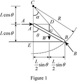
Write the expression for the distances
Write the expression for the distances
Write the expression of Pythagoras theorem in the triangle
Conclusion:
Use equation (I) and (II) in (III).
Use equation (IV), (V) and (VII) in (VI).
Simplify equation (VIII).
The expression for the equilibrium condition of the rod is,
Given that the length of the rod is
Substitute
Therefore, the angle
(b)
The reaction at
(b)
Answer to Problem 4.90P
The reaction at
Explanation of Solution
The free-body diagram corresponding to the arrangement is given in Figure 1.
Write the expression for computing the angle
Use equation (IV) and (VII) in (X).
At the equilibrium condition, a force triangle can be drawn using
Conclusion:
Substitute
The force triangle using
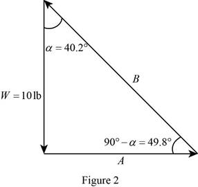
Write the trigonometric relation for determining
Write the trigonometric relation for det4ermoini ng
Substitute
and,
The reaction at
Therefore, the reaction at
Want to see more full solutions like this?
Chapter 4 Solutions
Vector Mechanics for Engineers: Statics, 11th Edition


- The axis of the three-hinge arch ABC is a parabola with vertex at B . Knowing that P= 112 kN and Q = 140 kN, determine (a) the components of the reaction at A, (b) the components of the force exerted at B on segment AB.arrow_forwardThe axis of the three-hinge arch ABC is a parabola with vertex at B.Knowing that P= 112 kN and Q =140 kN, determine (a) the components of the reaction at A, (b) the components of the force exerted at B on segment AB.arrow_forwardA slender rod AB is attached to two collars A and B that can move freely along the guide rods shown. Knowing that β= 30° and P =100 N and Q = 25 N, determine the value of the angle 0 corresponding to equilibrium.arrow_forward
- the frame shown supports part of the roof of a small building. Knowing that the tension in the cable is 150 kN, determine the reaction at the fixed end E.arrow_forwardA uniform rod AB of length 2R rests inside a hemispherical bowl of radius R as shown. Neglecting friction, determine the angle 0 corresponding to equilibrium.arrow_forwardKnowing that the pulley has a radius of 75 mm, determine the components of the reactions at A and B.arrow_forward
- An 8-kg slender rod of length L is attached to collars that can slide freely along the guides shown. Knowing that the rod is in equilibrium and that β= 30°, determine (a) the angle 0 that the rod forms with the vertical, (b) the reactions at A and B.arrow_forward4.108 - A 2250 N marquee, 2,4 x 3 m, is held in a horizontal position bytwo horizontal hinges at A and B and by a cable CD attached to a point D located 1,5m directly above B. Determine the tension in the cable and the components of the reactions at the hinges.arrow_forwardTwo identical rods ABC and DBE are connected by a pin at B and by a spring CE . Knowing that the spring is 4 in. long when unstretched and that the constant of the spring is 8 lb/in., determine the distance x corresponding to equilibrium when a 24-lb load is applied at E as shown.arrow_forward
- The press shown is used to emboss a small seal at E. Knowing that P= 250 N, determine (a) the vertical component of the force exerted on the seal, (b) the reaction at A.arrow_forward4.7 A hand truck is used to move a compressed-air cylinder. Knowing that the combined weight of the truck and cylinder is 180 lb. determine (a) the vertical force P that should be applied to the handle to maintain the cylinder in the position shown, (b) the corresponding reaction at each of the two wheels.arrow_forwardA spring AB of constant k is attached to two identical gears as shown. Knowing that the spring is undeformed when 0= 0, determine two values of the angle 0 corresponding to equilibrium when P= 30 lb, a= 4 in., b= 3 in., r= 6 in., and k= 5 lb/in. State in each case whether the equilibrium is stable, unstable, or neutral.arrow_forward
 Elements Of ElectromagneticsMechanical EngineeringISBN:9780190698614Author:Sadiku, Matthew N. O.Publisher:Oxford University Press
 Mechanics of Materials (10th Edition)Mechanical EngineeringISBN:9780134319650Author:Russell C. HibbelerPublisher:PEARSON
 Thermodynamics: An Engineering ApproachMechanical EngineeringISBN:9781259822674Author:Yunus A. Cengel Dr., Michael A. BolesPublisher:McGraw-Hill Education
 Control Systems EngineeringMechanical EngineeringISBN:9781118170519Author:Norman S. NisePublisher:WILEY
 Mechanics of Materials (MindTap Course List)Mechanical EngineeringISBN:9781337093347Author:Barry J. Goodno, James M. GerePublisher:Cengage Learning
 Engineering Mechanics: StaticsMechanical EngineeringISBN:9781118807330Author:James L. Meriam, L. G. Kraige, J. N. BoltonPublisher:WILEY