Vector Mechanics for Engineers: Statics, 11th Edition
11th Edition
ISBN: 9780077687304
Author: Ferdinand P. Beer, E. Russell Johnston Jr., David Mazurek
Publisher: McGraw-Hill Education
bartleby

Concept explainers

bartleby

Videos

Question
Book Icon
Chapter 4.3, Problem 4.110P
To determine

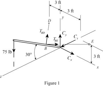
Find the tension in each brace and the reaction at C.

Expert Solution & Answer
Check Mark

Answer to Problem 4.110P

The tension in brace BD is TBD=176.8lb_.

The tension in brace BE is TBE=176.8lb_.

The reaction at C is C=(50lb)j+(216.5lb)k_.

Explanation of Solution

Given information:

The length of the flag pole AC is 10ft.

The inclination of the flag pole AC is 30°.

The distance BC is 3ft.

Calculation:

Assumption:

Apply the sign convention for calculating the equations of equilibrium as shown below.

  • For the horizontal forces equilibrium condition, take the force acting towards right side as positive (+) and the force acting towards left side as negative ().
  • For the vertical forces equilibrium condition, take the upward force as positive (+) and the downward force as negative ().
  • For moment equilibrium condition, take the clockwise moment as negative and counterclockwise moment as positive.

Sketch the Free Body Diagram as shown in Figure 1.

Vector Mechanics for Engineers: Statics, 11th Edition, Chapter 4.3, Problem 4.110P

Calculate the position vector (r) as shown below.

The position of A is;

rA=(10sin30°)j(10cos30°)k=(5ft)j(8.66ft)k

The position of B is;

rB=(3sin30°)j+(3cos30°)k=(1.5ft)j+(2.598ft)k

The position of D is;

rD=(3ft)i+(3ft)j

The position of E is;

rE=(3ft)i+(3ft)j

Calculate the position of brace BD as shown below.

BD=rDrB

Substitute (3ft)i+(3ft)j for rD and (1.5ft)j+(2.598ft)k for rB.

BD=[(3ft)i+(3ft)j][(1.5ft)j+(2.598ft)k]=(3ft)i+(1.5ft)j(2.598ft)k

Calculate the length of brace BD as shown below.

BD=(3)2+(1.5)2+(2.598)2=17.999604=4.243ft

Calculate the position of brace BE as shown below.

BE=rErB

Substitute (3ft)i+(3ft)j for rB and (1.5ft)j+(2.598ft)k for rB.

BE=[(3ft)i+(3ft)j][(1.5ft)j+(2.598ft)k]=(3ft)i+(1.5ft)j(2.598ft)k

Calculate the length of brace BE as shown below.

BE=(3)2+(1.5)2+(2.598)2=17.999604=4.243ft

Calculate the tension in brace BD (TBD) as shown below.

TBD=TBDBDBD

Substitute (3ft)i+(1.5ft)j(2.598ft)k for BD and 4.243ft for BD.

TBD=TBD3i+1.5j2.598k4.243=TBD(0.707i+0.3535j0.6123k)

Calculate the tension in brace BE (TBE) as shown below.

TBE=TBEBEBE

Substitute (3ft)i+(1.5ft)j(2.598ft)k for BE and 4.243ft for BE.

TBE=TBE3i+1.5j2.598k4.243=TBE(0.707i+0.3535j0.6123k)

Apply the Equations of Equilibrium as shown below.

Apply the equilibrium equation of moment about point C and equate to zero for equilibrium.

MC=0rB×TBD+rB×TBE+rA×(75j)=0

Substitute (5ft)j(8.66ft)k for rA, (1.5ft)j+(2.598ft)k for rB, TBD(0.707i+0.3535j0.6123k) for TBD, and TBE(0.707i+0.3535j0.6123k) for TBE.

[(1.5j+2.598k)×(TBD(0.707i+0.3535j0.6123k))+(1.5j+2.598k)×(TBE(0.707i+0.3535j0.6123k))+(5j8.66k)×(75j)]=0TBD|ijk01.52.5980.7070.35350.6123|+TBE|ijk01.52.5980.7070.35350.6123|+|ijk058.660750|=0[TBD(i(0.91850.9184)j(0+1.8368)+k(0+1.0605))+TBE(i(0.91850.9184)j(01.8368)+k(01.0605))+(i(0649.5)j(0)+k(0))]=0(TBD(1.8369i1.8368j+1.0605k)+TBE(1.8369i+1.8368j1.0605k)649.5i)=0

Multiply by 4.243.

(1.8369TBDi1.8368TBDj+1.0605TBDk1.8369TBEi+1.8368TBEj1.0605TBEk649.5i)=0{(1.8369TBD1.8369TBE649.5)i+(1.8368TBD+1.8368TBE)+(1.0605TBD1.0605TBEk)}=0

Resolve i, j, and k components as shown below.

Resolve j component.

1.8368TBD+1.8368TBE=01.8368TBD=1.8368TBETBD=TBE (1)

Resolve i component.

1.8369TBD1.8369TBE649.5=0

Substitute TBE for TAD.

1.8369TBE1.8369TBE649.5=03.6738TBE=649.5TBE=176.79lbTBE=176.79lb

Hence, the tension in brace BE is TBE=176.8lb_.

Calculate the tension in brace BD as shown below.

Substitute 176.8lb for TBE in Equation (1).

TBD=176.8lb

Hence, the tension in brace BD is TBD=176.8lb_.

Apply the Equations of Equilibrium as shown below.

Apply the equilibrium equation of forces in x-direction and equate to zero for equilibrium.

Fx=0Cx+176.8×(0.707)+176.8×0.707=0Cx=0

Apply the equilibrium equation of forces in y-direction and equate to zero for equilibrium.

Fy=0Cy+176.8×0.3535+176.8×0.353575=0Cy+50=0Cy=50lb

Apply the equilibrium equation of forces in z-direction and equate to zero for equilibrium.

Fz=0Cz+176.8×(0.6123)+176.8×(0.6123)=0Cz216.5=0Cz=216.5lb

Calculate the reaction at C as shown below.

C=Cxi+Cyj+Czk

Substitute 0 for Cx, 50lb for Cy, and 216.5lb for Cz.

C=(0)i+(50)j+(216.5)k=(50 lb)j+(216.5lb)k

Therefore, the reaction at C is C=(50 lb)j+(216.5lb)k_.

Want to see more full solutions like this?

Subscribe now to access step-by-step solutions to millions of textbook problems written by subject matter experts!

Chapter 4 Solutions

Vector Mechanics for Engineers: Statics, 11th Edition

Ch. 4.1 - 4.7 A T-shaped bracket supports the four loads...Ch. 4.1 - 4.8 For the bracket and loading of Prob. 4.7,...Ch. 4.1 - Three loads are applied as shown to a light beam...Ch. 4.1 - 4.10 Three loads are applied as shown to a light...Ch. 4.1 - 4.11 For the beam of Prob. 4.10, determine the...Ch. 4.1 - For the beam of Sample Prob. 4.2, determine the...Ch. 4.1 - The maximum allowable value of each of the...Ch. 4.1 - For the beam and loading shown, determine the...Ch. 4.1 - Prob. 4.15PCh. 4.1 - Prob. 4.16PCh. 4.1 - Prob. 4.17PCh. 4.1 - Prob. 4.18PCh. 4.1 - The bracket BCD is hinged at C and attached to a...Ch. 4.1 - The ladder AB, of length L and weight W, can be...Ch. 4.1 - 4.21 The 40-ft boom AB weighs 2 kips; the distance...Ch. 4.1 - A lever AB is hinged at C and attached to a...Ch. 4.1 - 4.23 and 4.24 For each of the plates and loadings...Ch. 4.1 - 4.23 and 4.24 For each of the plates and loadings...Ch. 4.1 - A rod AB, hinged at A and attached at B to cable...Ch. 4.1 - Fig. P4.25 and P4.26 4.26 A rod AB, hinged at A...Ch. 4.1 - Prob. 4.27PCh. 4.1 - Determine the reactions at A and C when (a) = 0,...Ch. 4.1 - Prob. 4.29PCh. 4.1 - Prob. 4.30PCh. 4.1 - Neglecting friction, determine the tension in...Ch. 4.1 - Fig. P4.31 and P4.32 4.32 Neglecting friction,...Ch. 4.1 - PROBLEM 4.33 A force P of magnitude 90 lb is...Ch. 4.1 - PROBLEM 4.34 Solve Problem 4,33 for a = 6 in,...Ch. 4.1 - Bar AC supports two 400-N loads as shown. Rollers...Ch. 4.1 - PROBLEM 4.36 A light bar AD is suspended from a...Ch. 4.1 - Prob. 4.37PCh. 4.1 - Prob. 4.38PCh. 4.1 - Prob. 4.39PCh. 4.1 - 4.40 A light bar AB supports a 15-kg block at its...Ch. 4.1 - 4.41 Two slots have been cut in plate DEF, and the...Ch. 4.1 - Prob. 4.42PCh. 4.1 - The rig shown consists of a 1200-lb horizontal...Ch. 4.1 - Fig. P4.43 4.44 For the rig and crate of Prob....Ch. 4.1 - A 175-kg utility pole is used to support at C the...Ch. 4.1 - Knowing that the tension in wire BD is 1300 N,...Ch. 4.1 - Fig. P4.46 and P4.47 4.47 Determine the range of...Ch. 4.1 - Beam AD carries the two 40-lb loads shown. The...Ch. 4.1 - Fig. P4.48 and P4.49 4.49 For the beam and loading...Ch. 4.1 - Prob. 4.50PCh. 4.1 - A uniform rod AB with a length of l and weight of...Ch. 4.1 - Rod AD is acted upon by a vertical force P at end...Ch. 4.1 - A slender rod AB with a weigh of W is attached to...Ch. 4.1 - 4.54 and 4.55 A vertical load P is applied at end...Ch. 4.1 - 4.54 and 4.55 A vertical load P is applied at end...Ch. 4.1 - A collar B with a weight of W can move freely...Ch. 4.1 - A 400-lb weight is attached at A to the lever...Ch. 4.1 - Prob. 4.58PCh. 4.1 - Eight identical 500 750-mm rectangular plates,...Ch. 4.1 - Prob. 4.60PCh. 4.2 - A 500-lb cylindrical tank, 8 ft in diameter, is to...Ch. 4.2 - 4.62.Determine the reactions at A and B when a =...Ch. 4.2 - Prob. 4.63PCh. 4.2 - Prob. 4.64PCh. 4.2 - Determine the reactions at B and C when a = 30 mm.Ch. 4.2 - Prob. 4.66PCh. 4.2 - Determine the reactions at B and D when b = 60 mm....Ch. 4.2 - For the frame and loading shown, determine the...Ch. 4.2 - A 50-kg crate is attached to the trolley-beam...Ch. 4.2 - One end of rod AB rests in the corner A and the...Ch. 4.2 - For the boom and loading shown, determine (a) the...Ch. 4.2 - Prob. 4.72PCh. 4.2 - Prob. 4.73PCh. 4.2 - Prob. 4.74PCh. 4.2 - Rod AB is supported by a pin and bracket at A and...Ch. 4.2 - Solve Prob. 4.75, assuming that the 170-N force...Ch. 4.2 - Prob. 4.77PCh. 4.2 - Using the method of Sec. 4.2B, solve Prob. 4.22....Ch. 4.2 - Knowing that = 30, determine the reaction (a) at...Ch. 4.2 - Prob. 4.80PCh. 4.2 - Determine the reactions at A and B when = 50....Ch. 4.2 - Determine the reactions at A and B when = 80.Ch. 4.2 - Rod AB is bent into the shape of an arc of circle...Ch. 4.2 - A slender rod of length L is attached to collars...Ch. 4.2 - Prob. 4.85PCh. 4.2 - Prob. 4.86PCh. 4.2 - A slender rod BC with a length of L and weight W...Ch. 4.2 - A thin ring with a mass of 2 kg and radius r = 140...Ch. 4.2 - Prob. 4.89PCh. 4.2 - Prob. 4.90PCh. 4.3 - Two tape spools are attached to an axle supported...Ch. 4.3 - A 12-m pole supports a horizontal cable CD and is...Ch. 4.3 - A 20-kg cover for a roof opening is hinged at...Ch. 4.3 - END-OF-SECTION PROBLEMS 4.91 Two transmission...Ch. 4.3 - Solve Prob. 4.91, assuming that the pulley rotates...Ch. 4.3 - A small winch is used to raise a 120-lb load. Find...Ch. 4.3 - 4.94 A 4 × 8-ft sheet of plywood weighing 34 lb...Ch. 4.3 - A 250 400-mm plate of mass 12 kg and a...Ch. 4.3 - Solve Prob. 4.95 for = 60. 4.95 A 250 400-mm...Ch. 4.3 - 4.97 The 20 × 20-in. square plate shown weighs 56...Ch. 4.3 - 4.98 The 20 × 20-in. square plate shows weighs 56...Ch. 4.3 - An opening in a floor is covered by a 1 1.2-m...Ch. 4.3 - PROBLEM 4.100 Solve Problem 4.99, assuming that...Ch. 4.3 - PROBLEM 4.101 Two steel pipes AB and BC, each...Ch. 4.3 - PROBLEM 4.102 For the pipe assembly of Problem...Ch. 4.3 - PROBLEM 4.103 The 24-lb square plate shown is...Ch. 4.3 - PROBLEM 4.104 The table shown weighs 30 lb and has...Ch. 4.3 - PROBLEM 4.105 A 10-ft boom is acted upon by the...Ch. 4.3 - PROBLEM 4.106 The 6-m pole ABC is acted upon by a...Ch. 4.3 - PROBLEM 4.107 Solve Problem 4.106 for a = 1.5 m....Ch. 4.3 - Prob. 4.108PCh. 4.3 - Prob. 4.109PCh. 4.3 - Prob. 4.110PCh. 4.3 - PROBLEM 4.111 A 48-in. boom is held by a...Ch. 4.3 - PROBLEM 4.112 Solve Problem 4.111, assuming that...Ch. 4.3 - PROBLEM 4.114 The bent rod ABEF is supported by...Ch. 4.3 - Prob. 4.114PCh. 4.3 - The horizontal platform ABCD weighs 60 lb and...Ch. 4.3 - PROBLEM 4.116 The lid of a roof scuttle weighs 75...Ch. 4.3 - PROBLEM 4.117 A 100-kg uniform rectangular plate...Ch. 4.3 - Solve Prob. 4.117, assuming that cable DCE is...Ch. 4.3 - PROBLEM 4.119 Solve Prob. 4.113, assuming that the...Ch. 4.3 - PROBLEM 4.120 Solve Prob. 4.115, assuming that the...Ch. 4.3 - PROBLEM 4.121 The assembly shown is used to...Ch. 4.3 - PROBLEM 4.122 The assembly shown is welded to...Ch. 4.3 - 4.123 The rigid L-shaped member ABC is supported...Ch. 4.3 - Prob. 4.124PCh. 4.3 - The rigid L-shaped member ABF is supported by a...Ch. 4.3 - Solve Prob. 4.125, assuming that the load at C has...Ch. 4.3 - Three rods are welded together to form a corner...Ch. 4.3 - Prob. 4.128PCh. 4.3 - Frame ABCD is supported by a ball-and-socket joint...Ch. 4.3 - Prob. 4.130PCh. 4.3 - Prob. 4.131PCh. 4.3 - PROBLEM 4.132 The uniform 10kg rod AB is supported...Ch. 4.3 - The frame ACD is supported by ball-and-socket...Ch. 4.3 - Solve Prob. 4.133, assuming that cable GBH is...Ch. 4.3 - Prob. 4.135PCh. 4.3 - Prob. 4.136PCh. 4.3 - Prob. 4.137PCh. 4.3 - The pipe ACDE is supported by ball-and-socket...Ch. 4.3 - Solve Prob. 4.138, assuming that wire DF is...Ch. 4.3 - Two 2 4-ft plywood panels, each with a weight of...Ch. 4.3 - Solve Prob. 4.140, subject to the restriction that...Ch. 4 - A 3200-lb forklift truck is used to lift a 1700-lb...Ch. 4 - The lever BCD is hinged at C and attached to a...Ch. 4 - Determine the reactions at A and B when (a) h =0,...Ch. 4 - Neglecting friction and the radius of the pulley,...Ch. 4 - PROBLEM 4.146 Bar AD is attached at A and C to...Ch. 4 - PROBLEM 4.147 A slender rod AB, of weight W, is...Ch. 4 - PROBLEM 4.148 Determine the reactions at A and B...Ch. 4 - For the frame and loading shown, determine the...Ch. 4 - PROBLEM 4.150 A 200-mm lever and a 240-mm-diameter...Ch. 4 - The 45-lb square plate shown is supported by three...Ch. 4 - The rectangular plate shown weighs 75 lb and is...Ch. 4 - A force P is applied to a bent rod ABC, which may...
Knowledge Booster
Background pattern image
Mechanical Engineering
Learn more about
Need a deep-dive on the concept behind this application? Look no further. Learn more about this topic, mechanical-engineering and related others by exploring similar questions and additional content below.
Recommended textbooks for you
Text book image
Elements Of Electromagnetics
Mechanical Engineering
ISBN:9780190698614
Author:Sadiku, Matthew N. O.
Publisher:Oxford University Press
Text book image
Mechanics of Materials (10th Edition)
Mechanical Engineering
ISBN:9780134319650
Author:Russell C. Hibbeler
Publisher:PEARSON
Text book image
Thermodynamics: An Engineering Approach
Mechanical Engineering
ISBN:9781259822674
Author:Yunus A. Cengel Dr., Michael A. Boles
Publisher:McGraw-Hill Education
Text book image
Control Systems Engineering
Mechanical Engineering
ISBN:9781118170519
Author:Norman S. Nise
Publisher:WILEY
Text book image
Mechanics of Materials (MindTap Course List)
Mechanical Engineering
ISBN:9781337093347
Author:Barry J. Goodno, James M. Gere
Publisher:Cengage Learning
Text book image
Engineering Mechanics: Statics
Mechanical Engineering
ISBN:9781118807330
Author:James L. Meriam, L. G. Kraige, J. N. Bolton
Publisher:WILEY
Solids: Lesson 53 - Slope and Deflection of Beams Intro; Author: Jeff Hanson;https://www.youtube.com/watch?v=I7lTq68JRmY;License: Standard YouTube License, CC-BY