
Concept explainers
Videos
(a) Obtain a value for the Thévenin equivalent resistance seen looking into the open terminals of the circuit in Fig. 5.76 by first finding Voc and Isc. (b) Connect a 1 A test source to the open terminals of the original circuit after shorting the voltage source, and use this to obtain RTH. (c) Connect a 1 V test source to the open terminals of the original circuit after again zeroing the 2 V source, and use this now to obtain RTH.
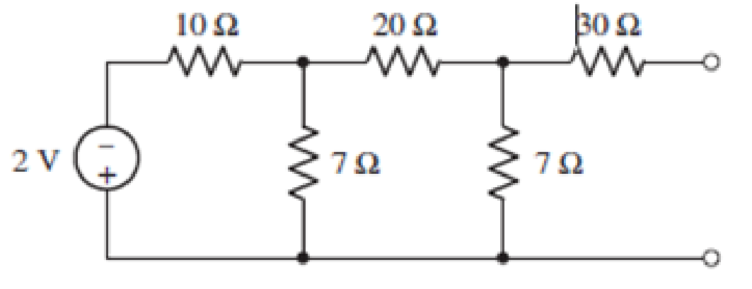
FIGURE 5.76
(a)
Find the value for the Thevenin’s equivalent resistance seen looking into the open terminals of the circuit by first finding
Answer to Problem 35E
The Thevenin’s equivalent resistance is
Explanation of Solution
Calculation:
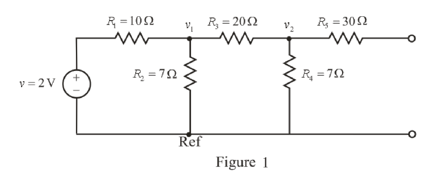
The redrawn circuit diagram is given in Figure 1.
Apply KCL ay node 1,
Here,
Substitute
Rearrange for
Apply KCL at node 2,
Here,
Substitute
Rearrange for
Substitute
Rearrange for
Substitute
So, the voltage
The redrawn circuit diagram is given in Figure 2,
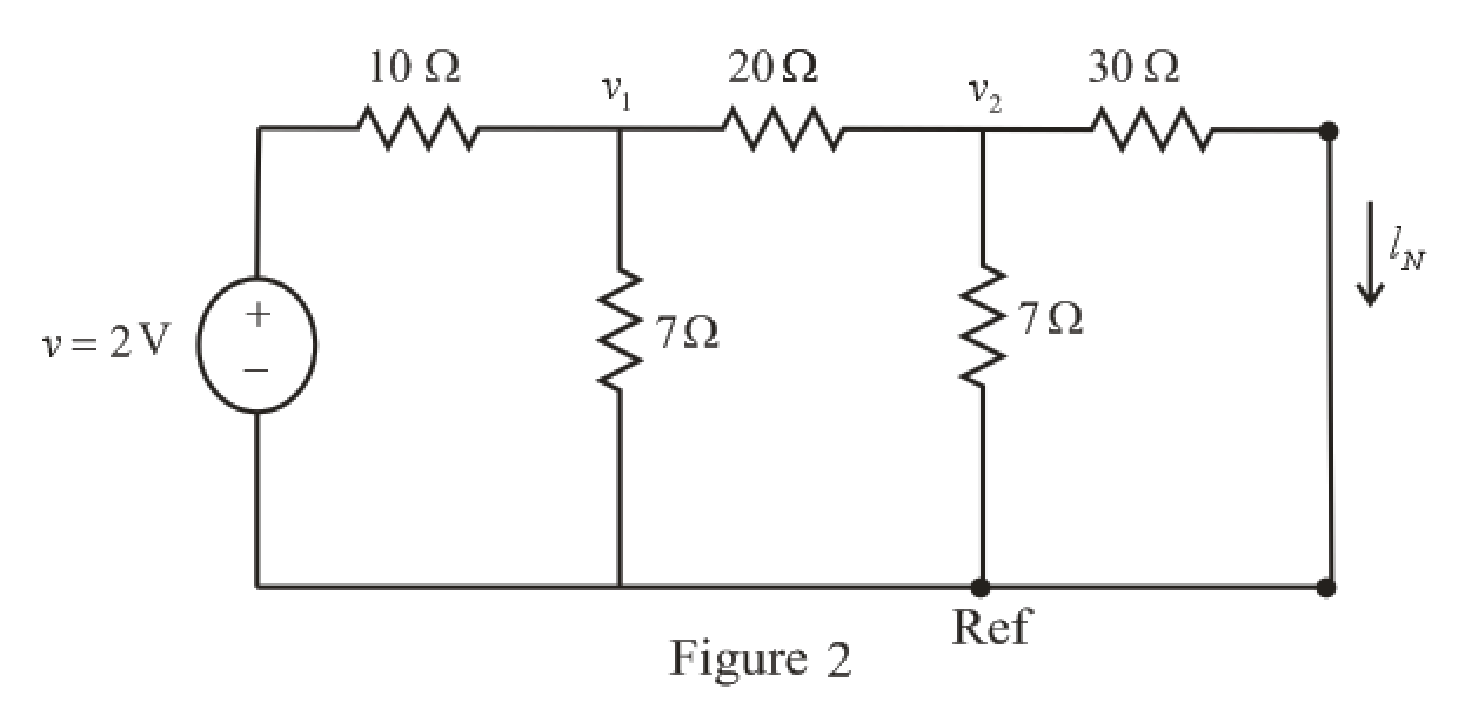
Refer to the redrawn Figure 2,
Apply KCL at node 1,
Substitute
Rearrange for
Apply KCL at node 2,
Here,
Substitute
Rearrange for
Substitute
The expression for the current flowing through
Here,
Substitute
So, the current
The expression for the Thevenin’s equivalent resistance is as follows,
Here,
Substitute
Conclusion:
Thus, the Thevenin’s equivalent resistance is
(b)
Connect a
Answer to Problem 35E
The Thevenin’s equivalent resistance is
Explanation of Solution
Calculation:
The redrawn circuit diagram is given in Figure 3,
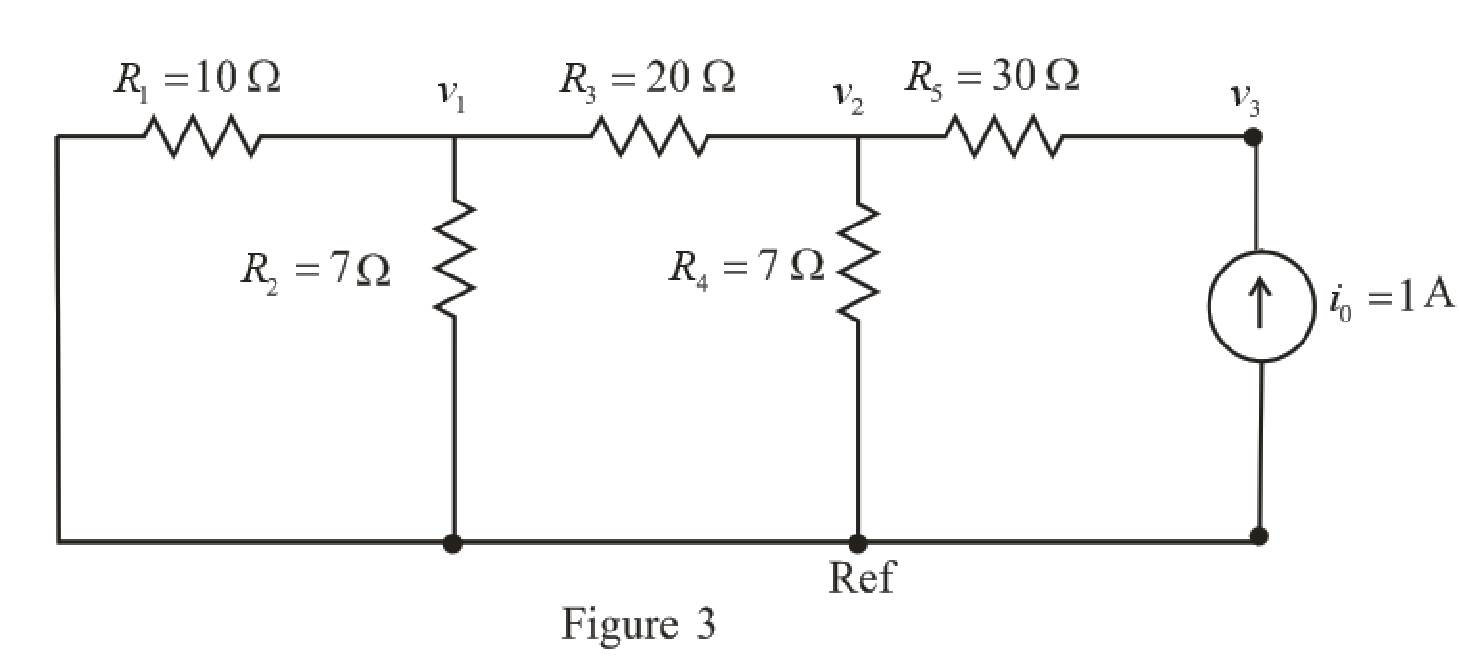
Refer to the redrawn Figure 3,
Apply KCL ay node 1,
Here,
Substitute
Rearrange for
Apply KCL at node 2,
Here,
Substitute
Rearrange for
The expression for the current flowing through
Here,
Substitute 1 A for
Rearrange for
Substitute
Substitute
Rearrange for
Substitute
The expression for the Thevenin’s equivalent resistance is as follows,
Here,
Substitute 35.43 V for
Conclusion:
Thus, the Thevenin’s equivalent resistance is
(c)
Connect a 1 V test source to the open terminals of the original circuit after again
zeroing the 2 V source, and use this now to obtain
Answer to Problem 35E
The Thevenin’s equivalent resistance is
Explanation of Solution
Calculation:
The redrawn circuit diagram is given in Figure 4,
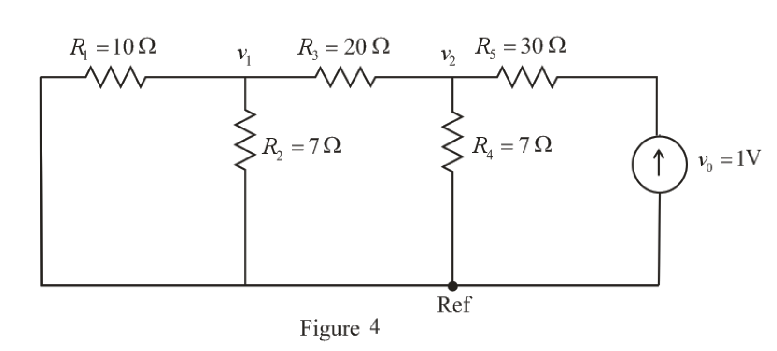
Refer to the redrawn Figure 4,
Apply KCL ay node 1,
Here,
Substitute
Rearrange for
Apply KCL at node 2,
Here,
Substitute
Rearrange for
Substitute
The expression for the Thevenin’s equivalent resistance is as follows,
Here,
Substitute 0.1532 V for
Conclusion:
Thus, the Thevenin’s equivalent resistance is
Want to see more full solutions like this?
Chapter 5 Solutions
Engineering Circuit Analysis


- For each configuration in Fig. 5.85, find the individual (not combinations of) elements (voltages sources and/or resistors) that are in series. If necessary, use the fact that elements in series have the same current. Simply list those that satisfy the conditions for a series relationship.arrow_forwardFind the K value range that ensures the stability of the system given below. Plot the root locus curve to scale for the range of K values obtained. Then investigate the system stability both numerically and graphically for the K value given. Write the values you obtained in the following places.1-)What is the stability K value range?2-)Draw the Root-Location Curve for the K value range that provides the stability.3-)Write the poles obtained for the given K value.4-)What is the stability of the System (Stable / Unstable / Marginally Stable) for a given K value?(please solve i need help)arrow_forwardDetermine the total resistance RsubT, using equivalent three terminal networks.arrow_forward
- Know how to design simple voltage-divider and currentdivider circuits How much power is dissipated in the 25 kΩ resistor if the load terminalsare accidentally short-circuited?arrow_forwardFor the circuit given below, let VBEQ=0.7 V, then the Q-point(VCEQ,ICEQ) equals:arrow_forwarddraw a qpsk demodulation circuit using circuit components for instance resistors, capacitors, transistors etcarrow_forward
- State the Thevenin's theorem and draw the Thevenin equivalent circuit cross the 6Ω loadresistance shown in Fig 5.arrow_forwardIf in the circuit of Example 5.5 the value of R, is doubled (to 13.1 k52), find approximate values for I, and V» Ans. 0.15 mA: 0.05 V Need workarrow_forwardFor the circuit below, calculate the requested values, considering a β = 200: a) IB, IE, VCE ,re ,AV, Zo, Ziarrow_forward
- For the series configuration in Fig. 5.92, constructed using standard value resistors: a.) Without making a single calculation, which resistive element will have the most voltage across it? Which will have the least? b.) Which resistor will have the most impact on the total resistance and the resulting current? Find the total resistance and the current.arrow_forward1. A thyristor operating from a peak supply voltage of 400 V has the followingspecifications:Repetitive peak current, Ip = 200 A, = 50 A/µs, = 200 V/ µs. Choosing a factor safety forthe above-mentioned parameters, design a suitable snubber circuit. The minimum valueof load resistance is 10 Ω. 2. A boost converter with vin = 12 V is required to be designed for a 100 W rating. If theoutput voltage is maintained at 96 V, find out load resistance and duty ratio. Furtherdesign the filter components in consideration with a ripple of 10% and 5% in inputcurrent and output voltage. Take the switching frequency be 30 kHz. 3. Following are the specifications of a thyristor operating from a peak voltage supply of500 V: Repetitive peak current, Ip = 250 A, = 60 A/µs, = 200 V/µs. Take the factor ofsafety of 2 for the three specifications mentioned above. Design a suitable snubber circuitif the minimum load resistance is 20 Ω. Take ξ = 0.65. 4. A buck–boost converter operating at 20 kHz, L = 0.05 mH.…arrow_forward12/ A junction in a circuit where two or more circuit elements are connected together is known as Node. Select one: True Falsearrow_forward
 Introductory Circuit Analysis (13th Edition)Electrical EngineeringISBN:9780133923605Author:Robert L. BoylestadPublisher:PEARSON
 Delmar's Standard Textbook Of ElectricityElectrical EngineeringISBN:9781337900348Author:Stephen L. HermanPublisher:Cengage Learning
 Programmable Logic ControllersElectrical EngineeringISBN:9780073373843Author:Frank D. PetruzellaPublisher:McGraw-Hill Education
 Fundamentals of Electric CircuitsElectrical EngineeringISBN:9780078028229Author:Charles K Alexander, Matthew SadikuPublisher:McGraw-Hill Education
 Electric Circuits. (11th Edition)Electrical EngineeringISBN:9780134746968Author:James W. Nilsson, Susan RiedelPublisher:PEARSON
 Engineering ElectromagneticsElectrical EngineeringISBN:9780078028151Author:Hayt, William H. (william Hart), Jr, BUCK, John A.Publisher:Mcgraw-hill Education,