
Concept explainers
Videos
Employ Δ–Y conversion techniques as appropriate to determine Rin as labeled in Fig. 5.101.
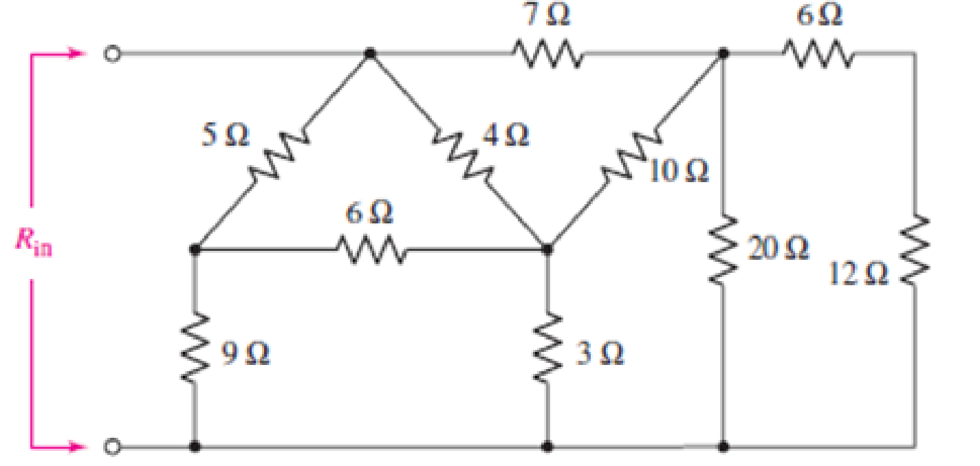
FIGURE 5.101
Employ Δ–Y conversion techniques as appropriate to determine
Answer to Problem 62E
The value of
Explanation of Solution
Formula used:
The expression for the equivalent resistor when resistors are connected in series is as follows:
Here,
The expression for the equivalent resistor when resistors are connected in parallel is as follows:
Here,
The
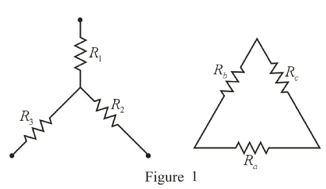
Refer to the redrawn Figure 1:
The expression for the conversion of
Here,
The expression for the conversion of
Calculation:
The redrawn circuit diagram is given in Figure 2:
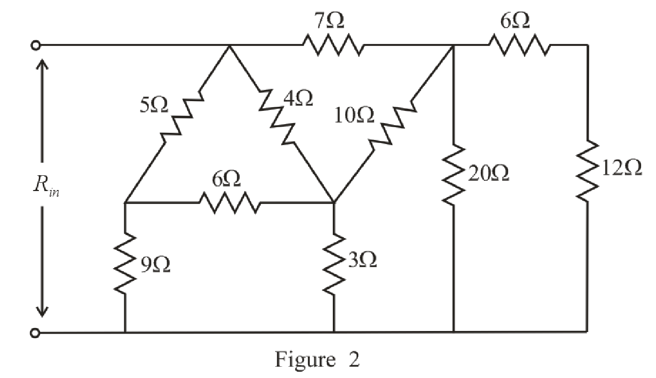
Refer to the redrawn Figure 2:
Substitute
The simplified circuit diagram is given in Figure 3.
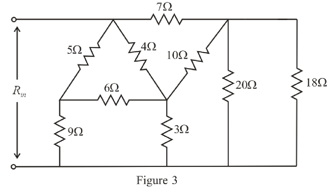
Refer to the redrawn Figure 3:
Substitute
Rearrange the equation for
The simplified circuit diagram is given in Figure 4.
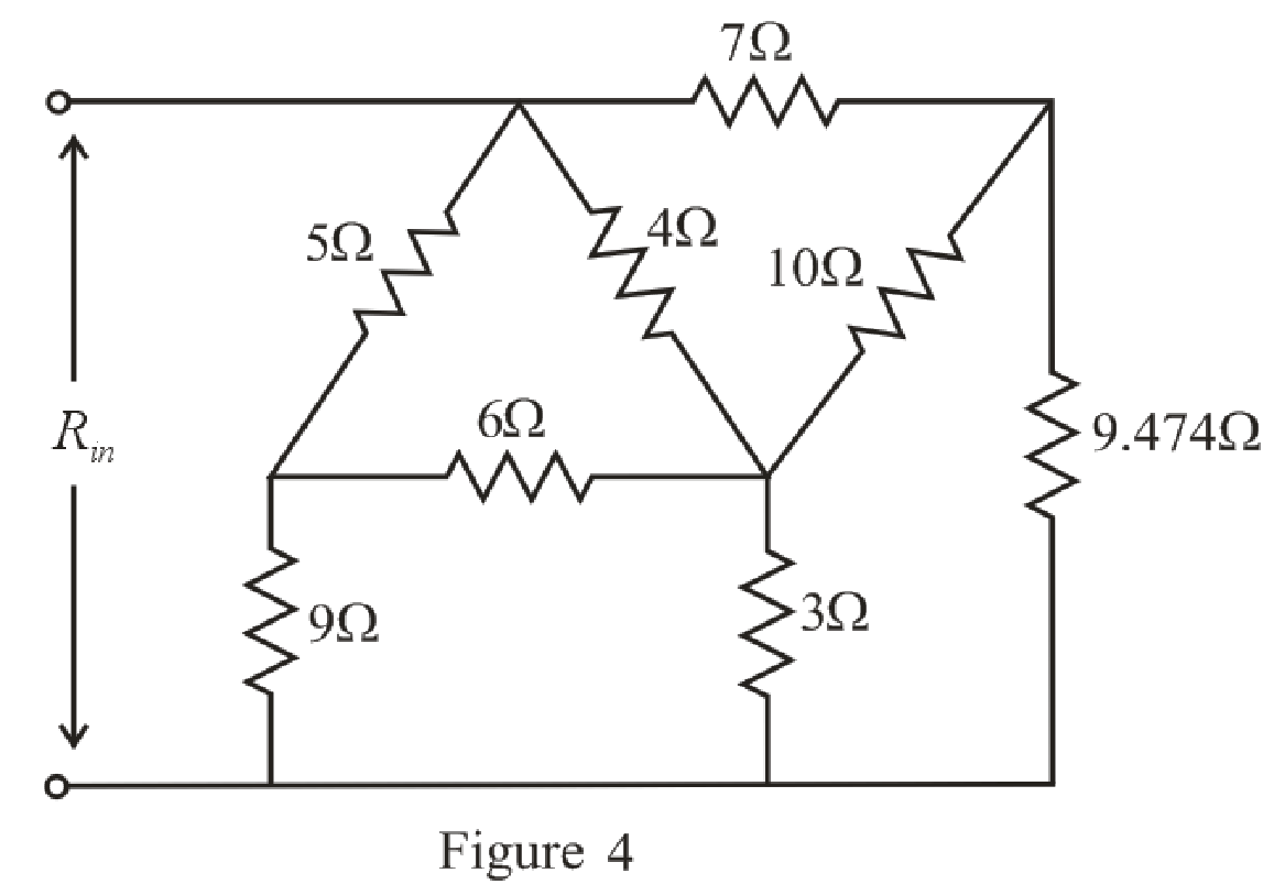
Refer to the redrawn Figure 4:
The
Substitute
Substitute
Substitute
The simplified circuit diagram is given in Figure 5:
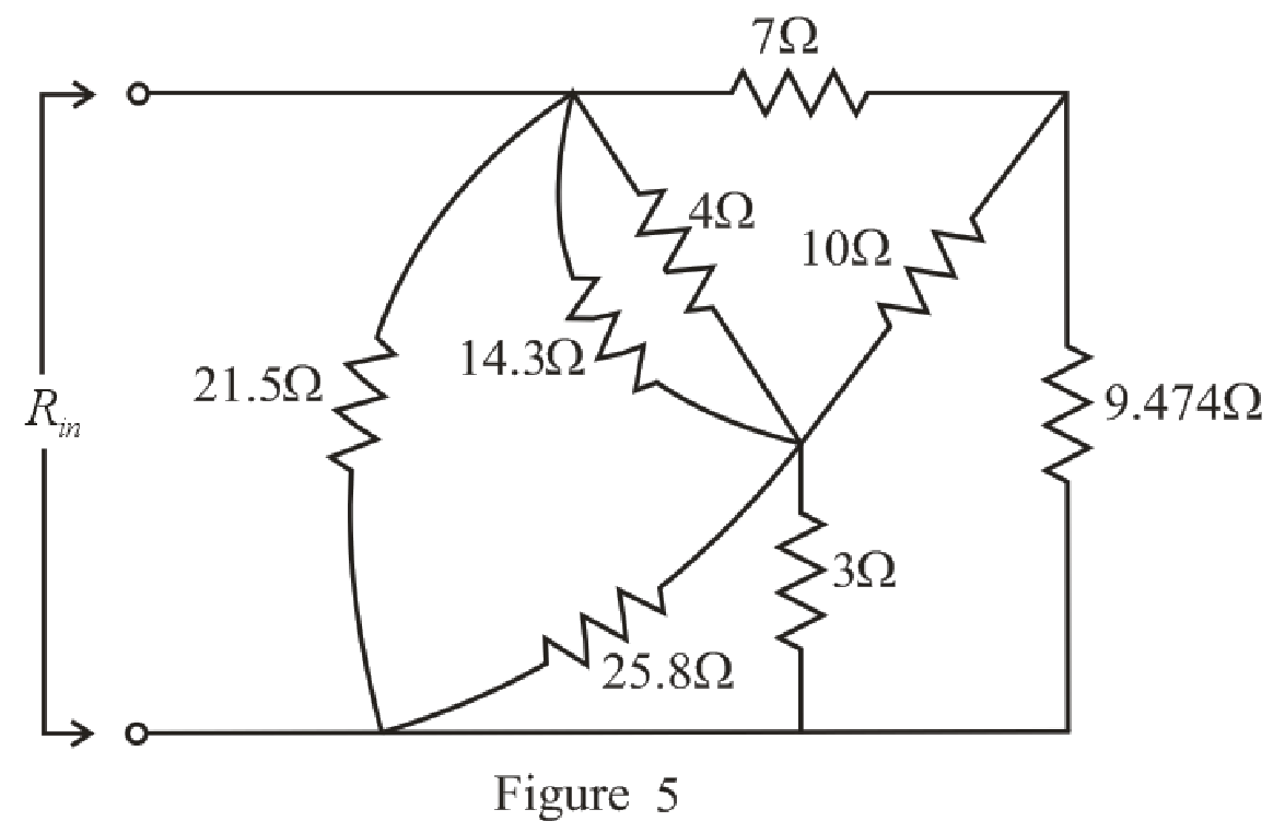
Refer to the redrawn Figure 5:
Substitute
Rearrange the equation for
Substitute
Rearrange the equation for
The simplified circuit diagram is given in Figure 6.
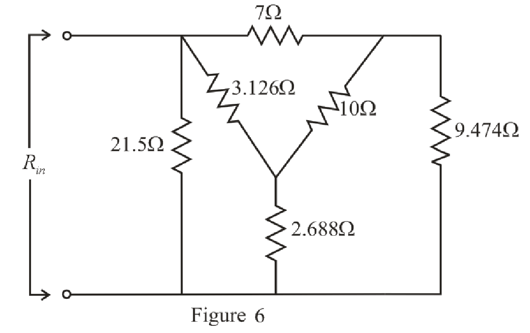
Refer to the redrawn Figure 6:
Substitute
Substitute
Substitute
The simplified circuit diagram is given in Figure 7.
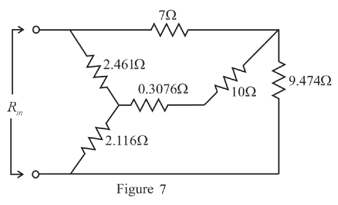
Refer to the redrawn Figure 7:
Substitute
The simplified circuit diagram is given in Figure 8:
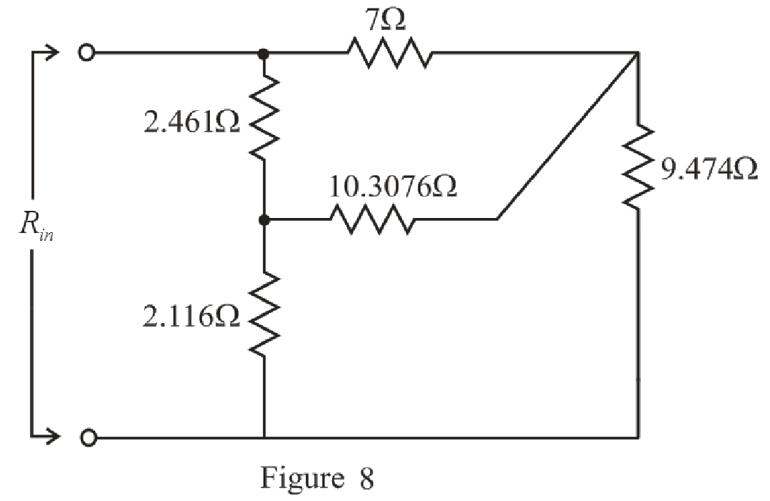
Refer to the redrawn Figure 8:
The
Substitute
Substitute
Substitute
The simplified circuit diagram is given in Figure 9:
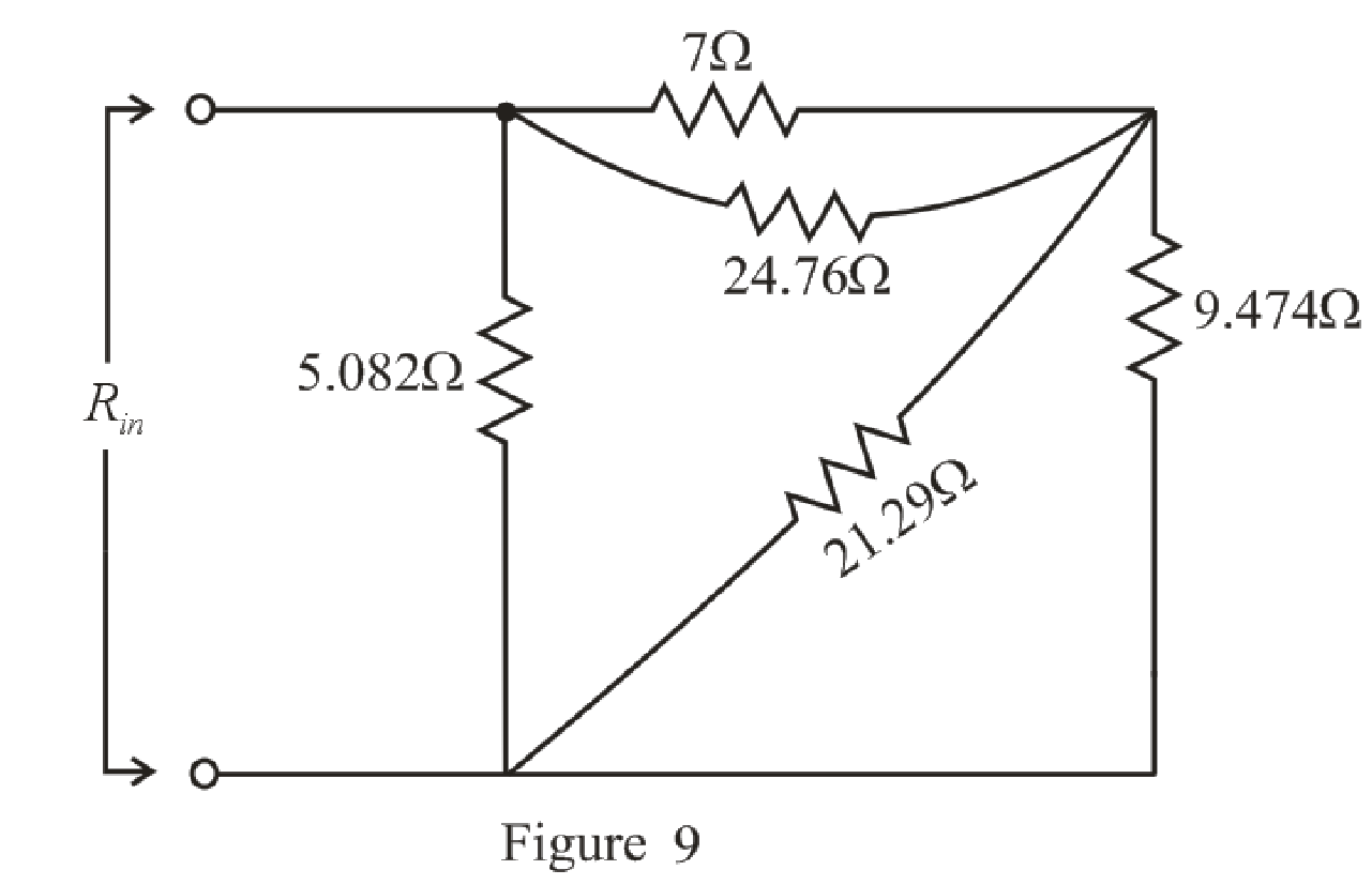
Refer to the redrawn Figure 9:
Substitute
Rearrange the equation for
Substitute
Rearrange the equation for
The simplified circuit diagram is given in Figure 10.
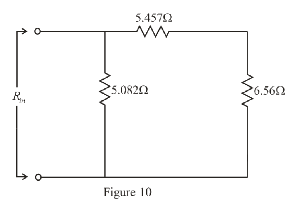
Refer to the redrawn Figure 10:
Substitute
The simplified circuit diagram is given in Figure 11.
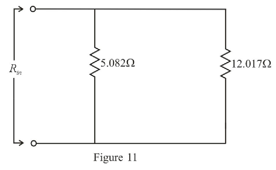
Refer to the redrawn Figure 11:
Substitute
Rearrange the equation for
The simplified circuit diagram is given in Figure 12.
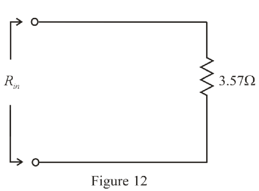
Conclusion:
Thus, the value of
Want to see more full solutions like this?
Chapter 5 Solutions
Engineering Circuit Analysis
Additional Engineering Textbook Solutions
Electric Motors and Control Systems
Basic Engineering Circuit Analysis
ANALYSIS+DESIGN OF LINEAR CIRCUITS(LL)
Microelectronics: Circuit Analysis and Design
Electric machinery fundamentals
Electrical Engineering: Principles & Applications (7th Edition)


- If in the circuit of Example 5.5 the value of R, is doubled (to 13.1 k52), find approximate values for I, and V» Ans. 0.15 mA: 0.05 V Need workarrow_forwardFor each configuration in Fig. 5.85, find the individual (not combinations of) elements (voltages sources and/or resistors) that are in series. If necessary, use the fact that elements in series have the same current. Simply list those that satisfy the conditions for a series relationship.arrow_forwardCalculate input impedance Zwe of circuit with ideal transformed (Fig. 5.19). Assume: R=1Ω, XL=1Ω, XC=2Ω.arrow_forward
- 5.37 Determine the output of the summing amplifier in Fig 5.74arrow_forwardQI:A: Design a multi-range ammeter of 0.5 and 1 Amp. using a PMMC(galvanometer) of 500 internal resistance and full-scale current of 1 ma. Show the way of connection with the load Rarrow_forwardEX:- re drow the network of fig. 5.183 for the AC respon with the re model inserted between the appropriate terminals include ro.arrow_forward
- ( NEED NEAT HANDWRITTEN SOLUTION ONLY OTHERWISE DOWNVOTE).In what region are these bipolar junction transistors working? for example my last 2 digit student number is 50.arrow_forward11 Kelvin Double Bridge is used for the measurement of larger value resistance. Select one: True Falsearrow_forwardThese are questions related operational amplifier. Please Solve all three sub-parts..Thank youarrow_forward
- 5. Kindly show complete solution so that I can understand. Give the given and what is ask. Thank you.arrow_forward12/ A junction in a circuit where two or more circuit elements are connected together is known as Node. Select one: True Falsearrow_forward1. A thyristor operating from a peak supply voltage of 400 V has the followingspecifications:Repetitive peak current, Ip = 200 A, = 50 A/µs, = 200 V/ µs. Choosing a factor safety forthe above-mentioned parameters, design a suitable snubber circuit. The minimum valueof load resistance is 10 Ω. 2. A boost converter with vin = 12 V is required to be designed for a 100 W rating. If theoutput voltage is maintained at 96 V, find out load resistance and duty ratio. Furtherdesign the filter components in consideration with a ripple of 10% and 5% in inputcurrent and output voltage. Take the switching frequency be 30 kHz. 3. Following are the specifications of a thyristor operating from a peak voltage supply of500 V: Repetitive peak current, Ip = 250 A, = 60 A/µs, = 200 V/µs. Take the factor ofsafety of 2 for the three specifications mentioned above. Design a suitable snubber circuitif the minimum load resistance is 20 Ω. Take ξ = 0.65. 4. A buck–boost converter operating at 20 kHz, L = 0.05 mH.…arrow_forward
 Introductory Circuit Analysis (13th Edition)Electrical EngineeringISBN:9780133923605Author:Robert L. BoylestadPublisher:PEARSON
 Delmar's Standard Textbook Of ElectricityElectrical EngineeringISBN:9781337900348Author:Stephen L. HermanPublisher:Cengage Learning
 Programmable Logic ControllersElectrical EngineeringISBN:9780073373843Author:Frank D. PetruzellaPublisher:McGraw-Hill Education
 Fundamentals of Electric CircuitsElectrical EngineeringISBN:9780078028229Author:Charles K Alexander, Matthew SadikuPublisher:McGraw-Hill Education
 Electric Circuits. (11th Edition)Electrical EngineeringISBN:9780134746968Author:James W. Nilsson, Susan RiedelPublisher:PEARSON
 Engineering ElectromagneticsElectrical EngineeringISBN:9780078028151Author:Hayt, William H. (william Hart), Jr, BUCK, John A.Publisher:Mcgraw-hill Education,