
Concept explainers
Videos
(a)
Find the power absorbed by a
(a)
Answer to Problem 66E
The power absorbed by a
Explanation of Solution
Given data:
The resistance of the load is
Formula used:
The expression for the equivalent resistor when resistors are connected in series is as follows:
Here,
The expression for the equivalent resistor when resistors are connected in parallel is as follows:
Here,
The
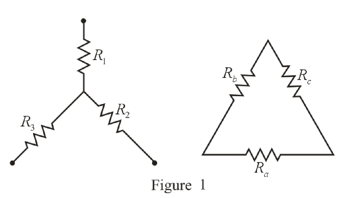
Refer to the redrawn Figure 1:
The expression for the conversion of
Here,
Calculation:
The redrawn circuit diagram is given in Figure 2.
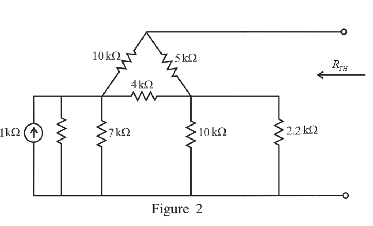
Refer to the redrawn Figure 2:
Substitute
Rearrange the equation for
Substitute
Rearrange the equation for
The simplified circuit diagram is given in Figure 3:
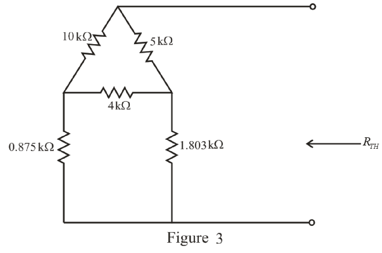
Refer to the redrawn Figure 3:
The
Substitute
Substitute
Substitute
The simplified circuit diagram is given in Figure 4.
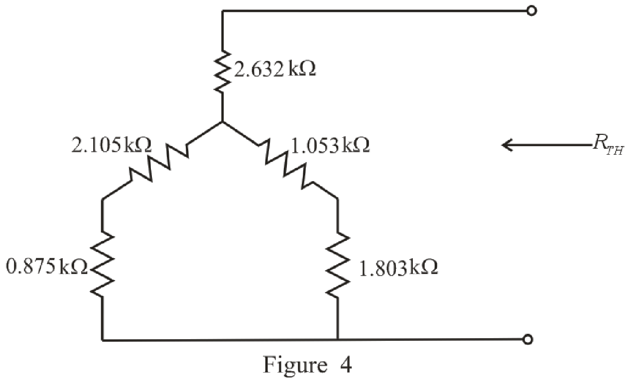
Refer to the redrawn Figure 4.
Substitute
Substitute
The simplified circuit diagram is given in Figure 5.
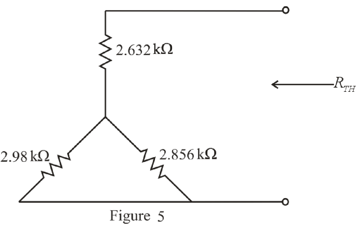
Refer to the redrawn Figure 5:
Substitute
Rearrange the equation for
The simplified circuit diagram is given in Figure 6.
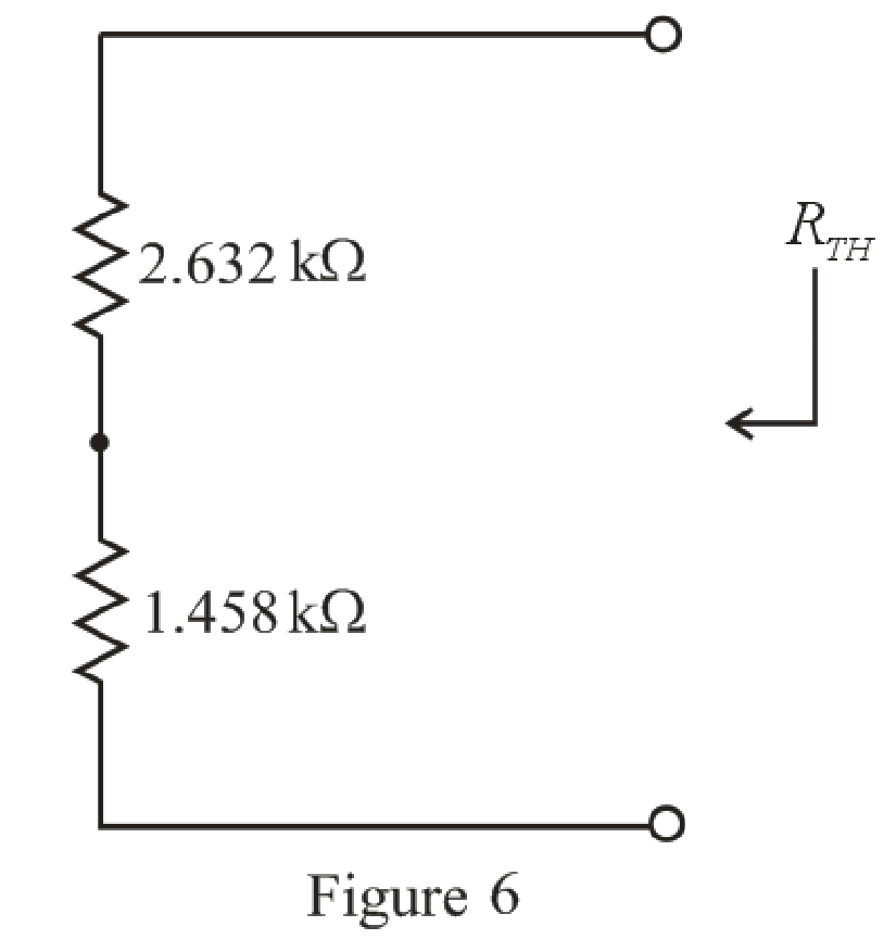
Refer to the redrawn Figure 6:
Substitute
The simplified circuit diagram is given in Figure 7.
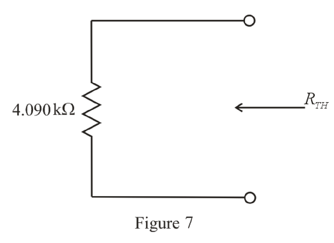
Refer to the redrawn Figure 7:
So, the Thevenin equivalent resistance is
The simplified circuit diagram is given in Figure 8.
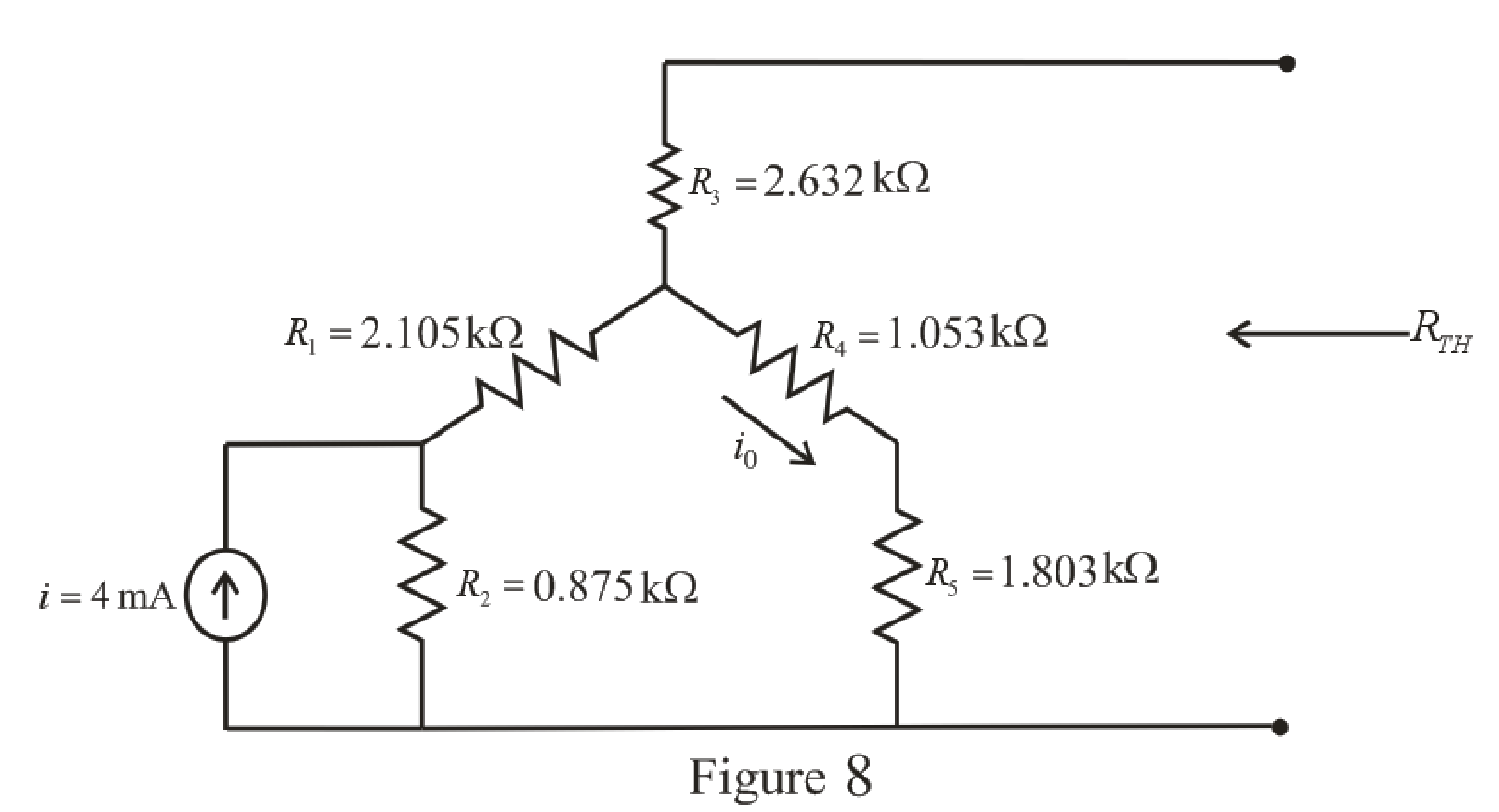
Refer to the redrawn Figure 8:
The
The expression for the current flowing through
Here,
Substitute
The expression for the Thevenin voltage is as follows:
Here,
Substitute
So, the Thevenin voltage of the circuit is
The redrawn circuit diagram is given in Figure 9.
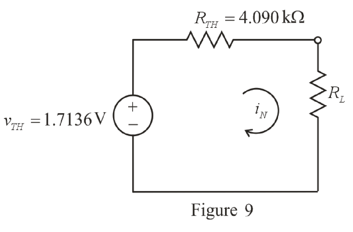
Refer to the redrawn Figure 9:
The expression for the power absorbed by the load resistor is as follows:
Here,
Substitute
Conclusion:
Thus, the power absorbed by a
(b)
Find the power absorbed by a
(b)
Answer to Problem 66E
The power absorbed by a
Explanation of Solution
Given data:
The resistance of the load is
Calculation:
Refer to the redrawn Figure 9:
Substitute
Conclusion:
Thus, the power absorbed by a
(c)
Find the power absorbed by a
(c)
Answer to Problem 66E
The power absorbed by a
Explanation of Solution
Given Data:
The resistance of the load is
Calculation:
Refer to the redrawn Figure 9:
Substitute
Conclusion:
Thus, the power absorbed by a
(d)
Find the power absorbed by a
(d)
Answer to Problem 66E
The power absorbed by a
Explanation of Solution
Given Data:
The resistance of the load is
Calculation:
Refer to the redrawn Figure 9:
Substitute
Conclusion:
Thus, the power absorbed by a
Want to see more full solutions like this?
Chapter 5 Solutions
Engineering Circuit Analysis


- If in the circuit of Example 5.5 the value of R, is doubled (to 13.1 k52), find approximate values for I, and V» Ans. 0.15 mA: 0.05 V Need workarrow_forwardIf the dark saturation current of a solar cell is 1.7X10⁻⁸ A/m2, the cell temperature is 27 oC, and the short-circuit current density is 250 A/m2, Vmax = 0.526 V, calculate the open-circuit voltage, Voc; current density at maximum power, Imax.arrow_forwardKindly provide CLEAR and COMPLETE solutions #5arrow_forward
- EX:- re drow the network of fig. 5.183 for the AC respon with the re model inserted between the appropriate terminals include ro.arrow_forward1. A thyristor operating from a peak supply voltage of 400 V has the followingspecifications:Repetitive peak current, Ip = 200 A, = 50 A/µs, = 200 V/ µs. Choosing a factor safety forthe above-mentioned parameters, design a suitable snubber circuit. The minimum valueof load resistance is 10 Ω. 2. A boost converter with vin = 12 V is required to be designed for a 100 W rating. If theoutput voltage is maintained at 96 V, find out load resistance and duty ratio. Furtherdesign the filter components in consideration with a ripple of 10% and 5% in inputcurrent and output voltage. Take the switching frequency be 30 kHz. 3. Following are the specifications of a thyristor operating from a peak voltage supply of500 V: Repetitive peak current, Ip = 250 A, = 60 A/µs, = 200 V/µs. Take the factor ofsafety of 2 for the three specifications mentioned above. Design a suitable snubber circuitif the minimum load resistance is 20 Ω. Take ξ = 0.65. 4. A buck–boost converter operating at 20 kHz, L = 0.05 mH.…arrow_forward7 Renewable Energy Sources are readily available everywhere, whole year round. Select one: True Falsearrow_forward
- QI:A: Design a multi-range ammeter of 0.5 and 1 Amp. using a PMMC(galvanometer) of 500 internal resistance and full-scale current of 1 ma. Show the way of connection with the load Rarrow_forwardengineering economics Valley Rendering, Inc. is considering purchasing a new flotation system for grease recovery. The company can finance a $150,000 system at 5% per year compound interest or 5.5% per year simple interest. If the total amount owed is due in a single payment at the end of 3 years, (a) which interest rate should the company select, and (b) how much is the difference in interest between the two schemes?arrow_forwardCan someone please clearly explain to me the difference between amps and watts using pictures? Please don't use words that people might not know about. Explain it as if you're teaching it to an elementary school student.arrow_forward
- The system of using helicopters to work on live power lines is based on the principle that electrical current seeks to flow into the ground. Select one: True Falsearrow_forward( NEED NEAT HANDWRITTEN SOLUTION ONLY OTHERWISE DOWNVOTE).In what region are these bipolar junction transistors working? for example my last 2 digit student number is 50.arrow_forwardPlease answer with brief explanation..and all subpart for like asap please.. 1) Voltage-level shifters are only needed when the voltage supply levels of the MCU and the peripheral(s) are at different level of voltages. i. True ii. False 2) LCD displays are constructed with two polarizing filters oriented in the same direction to allow the backlight to pass through. i. True ii. False 3) An active-matrix LCD displays incorporates a switching element into each individual cell via the: i. PNP transistor ii. Schmitt-trigger buffer iii. Thin filmed transistor iv. Bipolar capacitor.arrow_forward
 Introductory Circuit Analysis (13th Edition)Electrical EngineeringISBN:9780133923605Author:Robert L. BoylestadPublisher:PEARSON
 Delmar's Standard Textbook Of ElectricityElectrical EngineeringISBN:9781337900348Author:Stephen L. HermanPublisher:Cengage Learning
 Programmable Logic ControllersElectrical EngineeringISBN:9780073373843Author:Frank D. PetruzellaPublisher:McGraw-Hill Education
 Fundamentals of Electric CircuitsElectrical EngineeringISBN:9780078028229Author:Charles K Alexander, Matthew SadikuPublisher:McGraw-Hill Education
 Electric Circuits. (11th Edition)Electrical EngineeringISBN:9780134746968Author:James W. Nilsson, Susan RiedelPublisher:PEARSON
 Engineering ElectromagneticsElectrical EngineeringISBN:9780078028151Author:Hayt, William H. (william Hart), Jr, BUCK, John A.Publisher:Mcgraw-hill Education,