
Videos
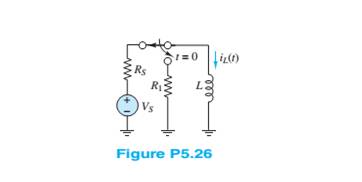
Assume that steady-state conditions exist in theCircuit shown in Figure P5.26 for
Want to see the full answer?
Check out a sample textbook solution
Chapter 5 Solutions
Principles and Applications of Electrical Engineering


- Solve for the mesh currents shown in Figure P5.54.arrow_forwardA resistor, an inductor, and a capacitor are connected in parallel to an ac source with voltage amplitude V and angular frequency v. Let the source voltage be given by v = Vcosvt. (a) Show that each of the instantaneous voltages vR, vL, and vC at any instant is equal to v and that i = iR + iL + iC, where i is the current through the source and iR, iL, and iC are the currents through the resistor, inductor, and capacitor, respectively. (b) What are the phases of iR, iL, and iC with respect to v? Use current phasors to represent i, iR, iL, and iC. In a phasor diagram, show the phases of these four currents with respect to v. (c) Use the phasor diagram of part (b) to show that the current amplitude I for the current i through the source is I = √(I2R) + (IC - IL)2 . (d) Show that the result of part (c) can be written as I = V/Z, with 1/Z = √ (1/R2) + [ωC - (1/ωL)]2.arrow_forwardThe Thévenin equivalent of a two-terminal network is shown in Figure P5.93. The frequency is f=60 Hz. We wish to connect a load across terminals that consists of a resistance and a capacitance in series such that the power delivered to the resistance is maximized. Find the value of the resistance and the value of the capacitance. Repeat Problem P5.93 with the load required to consist of a resistance and a capacitance in parallel.arrow_forward
- a) Find the final value for the capacitor voltage (Vc(∞ ))? b) Find the circuit time constant for t>0? c) Find an expression for the capcitor voltage for t>0?arrow_forwardAssume that S1 and S2 close at t = 0 in FigureP5.41.a. Find the capacitor voltage vC(t) at t = 0+. b. Find the time constant τ for t ≥ 0.c. Find an expression for vC(t), and sketch thefunction.d. Find vC(t) for each of the following values of t:0, τ, 2τ, 5τ, 10τ .arrow_forwardtopic: TRANSIENT RESPONSE OF RC, RL, AND RLC CIRCUITS How do capacitors and inductors in series and in parallel compare with resistors? For DC steady state analysis, what can be said about capacitors and inductors?arrow_forward
- Explain why we replace capacitances with open circuits and inductances with short circuits in dc steady-state analysis.arrow_forwardDraw the Thévenin and Norton equivalent circuits for Figure P5.91, labeling the elements and terminals.arrow_forwardWhich of the following is true regarding the behavior of capacitors when energized by a DC source? a. At transient state, the capacitor behaves as an open circuit. b. At transient state, the capacitor behaves as a short circuit. c. At steady-state, the capacitor behaves as a short circuit. d. At steady-state, the capacitor behaves as an open circuit.arrow_forward
- Solve for the node voltage shown in Figure P5.54.arrow_forwardHow does the product rule of differentiation (differential calculus) useful in Capacitance and Capacitors in Series and Parallel Connections?arrow_forwardWrite the differential equation for t > 0 for thecircuit of Figure P5.34arrow_forward
 Introductory Circuit Analysis (13th Edition)Electrical EngineeringISBN:9780133923605Author:Robert L. BoylestadPublisher:PEARSON
 Delmar's Standard Textbook Of ElectricityElectrical EngineeringISBN:9781337900348Author:Stephen L. HermanPublisher:Cengage Learning
 Programmable Logic ControllersElectrical EngineeringISBN:9780073373843Author:Frank D. PetruzellaPublisher:McGraw-Hill Education
 Fundamentals of Electric CircuitsElectrical EngineeringISBN:9780078028229Author:Charles K Alexander, Matthew SadikuPublisher:McGraw-Hill Education
 Electric Circuits. (11th Edition)Electrical EngineeringISBN:9780134746968Author:James W. Nilsson, Susan RiedelPublisher:PEARSON
 Engineering ElectromagneticsElectrical EngineeringISBN:9780078028151Author:Hayt, William H. (william Hart), Jr, BUCK, John A.Publisher:Mcgraw-hill Education,