
Concept explainers
Videos
The current
Answer to Problem 5.68HP
The expression for the current flowing through the inductor is
Explanation of Solution
Calculation:
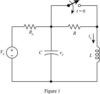
The given diagram is shown in Figure 1
The conversion from
The conversion from
The conversion from
The conversion from
The conversion from
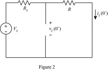
For time
The required diagram is shown in Figure 2
From above, the expression for the initial voltage across the capacitor is given by,
Substitute
The expression for the voltage across the capacitor for time
Substitute
The expression for the current flowing through the inductor for time
Substitute
The inductor opposes sudden change in the current, thus the current
Substitute
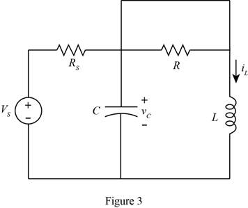
Close the switch and redraw the circuit for time
The required diagram is shown in Figure 3
The expression for the voltage across the inductor is given by,
Apply KVL to the top node.
Substitute
The standard second order equation for the differential equation.
From above and from equation (1), the angular frequency is derived as,
Substitute
The expression for the damping coefficient is given by,
Substitute
The value of
The expression for the output response equation of the inductor current is given by,
The expression for the forced response of the system is given by,
Substitute
The expression for the natural response for the system is give by,
Substitute
The expression to calculate the damping frequency of the circuit is given by,
Substitute
Substitute
Substitute
Substitute
The differentiation of equation (5) with respect to
Substitute
Substitute
Substitute
Conclusion:
Therefore, the expression for the current flowing through the inductor is
Want to see more full solutions like this?
Chapter 5 Solutions
Principles and Applications of Electrical Engineering


- Assuming that a nonzero ac voltage source is applied, what can you say about whether the power and reactive power are positive, negative, or zero for a pure capacitance in series with a pure inductance? Consider cases in which the impedance magnitude of the capacitance is greater than, equal to, or less than the impedance magnitude of the inductance. Repeat Problem P5.74 for the inductance and capacitance in parallel.arrow_forwardWrite the differential equation for t > 0 for thecircuit of Figure P5.27.arrow_forwardDescribe the steady-state similarities and differences of DC and AC circuits with purelyresistive elementsarrow_forward
- A resistor, an inductor, and a capacitor are connected in parallel to an ac source with voltage amplitude V and angular frequency v. Let the source voltage be given by v = Vcosvt. (a) Show that each of the instantaneous voltages vR, vL, and vC at any instant is equal to v and that i = iR + iL + iC, where i is the current through the source and iR, iL, and iC are the currents through the resistor, inductor, and capacitor, respectively. (b) What are the phases of iR, iL, and iC with respect to v? Use current phasors to represent i, iR, iL, and iC. In a phasor diagram, show the phases of these four currents with respect to v. (c) Use the phasor diagram of part (b) to show that the current amplitude I for the current i through the source is I = √(I2R) + (IC - IL)2 . (d) Show that the result of part (c) can be written as I = V/Z, with 1/Z = √ (1/R2) + [ωC - (1/ωL)]2.arrow_forwarda) Find the final value for the capacitor voltage (Vc(∞ ))? b) Find the circuit time constant for t>0? c) Find an expression for the capcitor voltage for t>0?arrow_forwardThe equation of the charge on the capacitor at any time t for an LRC series circuits is givenas a) Assume there is no initial charge and current, sketch the graph of the charge. b) What happen to the charge after a long time? c) State the transient and the steady state terms.arrow_forward
- Which of the following is true regarding the behavior of capacitors when energized by a DC source? a. At transient state, the capacitor behaves as an open circuit. b. At transient state, the capacitor behaves as a short circuit. c. At steady-state, the capacitor behaves as a short circuit. d. At steady-state, the capacitor behaves as an open circuit.arrow_forwardThe Thévenin equivalent of a two-terminal network is shown in Figure P5.93. The frequency is f=60 Hz. We wish to connect a load across terminals that consists of a resistance and a capacitance in series such that the power delivered to the resistance is maximized. Find the value of the resistance and the value of the capacitance. Repeat Problem P5.93 with the load required to consist of a resistance and a capacitance in parallel.arrow_forwardSolve for the node voltage shown in Figure P5.54.arrow_forward
- Determine (a) the amount of energy stored in each ofthe three capacitors shown in Fig. P5.22, (b) the equivalentcapacitance at terminals (a, b), and (c) the amount of energystored in the equivalent capacitorarrow_forwardtopic: TRANSIENT RESPONSE OF RC, RL, AND RLC CIRCUITS How do capacitors and inductors in series and in parallel compare with resistors? For DC steady state analysis, what can be said about capacitors and inductors?arrow_forwardWhat are two real-world consequences of having to amplify the input to a system so that the output reaches a desired steady-state value? Related to Electroncis & Circuitsarrow_forward
 Introductory Circuit Analysis (13th Edition)Electrical EngineeringISBN:9780133923605Author:Robert L. BoylestadPublisher:PEARSON
 Delmar's Standard Textbook Of ElectricityElectrical EngineeringISBN:9781337900348Author:Stephen L. HermanPublisher:Cengage Learning
 Programmable Logic ControllersElectrical EngineeringISBN:9780073373843Author:Frank D. PetruzellaPublisher:McGraw-Hill Education
 Fundamentals of Electric CircuitsElectrical EngineeringISBN:9780078028229Author:Charles K Alexander, Matthew SadikuPublisher:McGraw-Hill Education
 Electric Circuits. (11th Edition)Electrical EngineeringISBN:9780134746968Author:James W. Nilsson, Susan RiedelPublisher:PEARSON
 Engineering ElectromagneticsElectrical EngineeringISBN:9780078028151Author:Hayt, William H. (william Hart), Jr, BUCK, John A.Publisher:Mcgraw-hill Education,