
Bundle: Mechanics Of Materials, Loose-leaf Version, 9th + Mindtap Engineering, 1 Term (6 Months) Printed Access Card
9th Edition
ISBN: 9781337594318
Author: Barry J. Goodno; James M. Gere
Publisher: Cengage Learning
expand_more
expand_more
format_list_bulleted
Concept explainers
Videos
Textbook Question
Chapter 5, Problem 5.5.17P
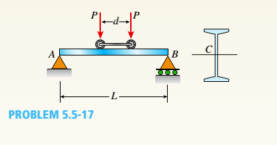
A simple beam A B of a span length L = 24 ft is subjected to two wheel loads acting at a distance d = 5 ft apart (see figure). Each wheel transmits a load P = 3.0 kips, and the carriage may occupy any position on the beam.
- Determine the maximum bending stress Gmaxdue to the wheel loads if the beam is an I-beam having section modulus S = 16.2 in3.
- If d = 5 ft. Find the required span length L to reduce the maximum stress in part (a) to 18 ksi.
- If L = 24 ft, Find the required wheel spacing s to reduce the maximum stress in part (a) to 18 ksi.
Expert Solution & Answer

Trending nowThis is a popular solution!

Chapter 5 Solutions
Bundle: Mechanics Of Materials, Loose-leaf Version, 9th + Mindtap Engineering, 1 Term (6 Months) Printed Access Card
Ch. 5 - A steel wire with a diameter of d = 1/16 in. is...Ch. 5 - A copper wire having a diameter ofd = 4 mm is bent...Ch. 5 - A 4.75-in, outside diameter polyethylene pipe...Ch. 5 - A cantilever beam AB is loaded by a couple M0at...Ch. 5 - A thin strip of steel with a length of L =19 in....Ch. 5 - A bar of rectangular cross section is loaded and...Ch. 5 - A simply supported beam with a length L = 10 ft...Ch. 5 - A cantilever beam is subjected to a concentrated...Ch. 5 - A thin strip of hard copper (E = 16,000 ksi)...Ch. 5 - A steel wire (E = 200 GPa) of a diameter d = L25...
Ch. 5 - A thin, high-strength steel rule (E = 30 x 10ft...Ch. 5 - A simply supported wood beam AB with a span length...Ch. 5 - Beam ABC has simple supports at A and B and an...Ch. 5 - A simply supported beam is subjected to a in early...Ch. 5 - Each girder of the lift bridge (sec figure) is 180...Ch. 5 - A freight-car axle AS is loaded approximately as...Ch. 5 - A seesaw weighing 3 lb/ft of length is occupied by...Ch. 5 - During construction of a highway bridge, the main...Ch. 5 - The horizontal beam ABC of an oil-well pump has...Ch. 5 - A railroad tie (or sleeper) is subjected to two...Ch. 5 - A fiberglass pipe is lifted by a sling, as shown...Ch. 5 - A small dam of height h = 2.0 m is constructed of...Ch. 5 - Determine the maximum tensile stress (7, (due to...Ch. 5 - Determine the maximum bending stress emaxdue to...Ch. 5 - A simple beam A B of a span length L = 24 ft is...Ch. 5 - Determine the maximum tensile stress erand maximum...Ch. 5 - A cantilever beam A3, loaded by a uniform load and...Ch. 5 - A canti lever beam A B of a n isosceles t...Ch. 5 - A cantilever beam, a C12 x 30 section, is...Ch. 5 - A frame ABC travels horizontally with an...Ch. 5 - A beam ABC with an overhang from B to C supports a...Ch. 5 - A cantilever beam AB with a rectangular cross...Ch. 5 - A beam with a T-section is supported and loaded as...Ch. 5 - Consider the compound beam with segments AB and...Ch. 5 - A small dam of a height h = 6 ft is constructed of...Ch. 5 - A foot bridge on a hiking trail is constructed...Ch. 5 - A steel post (E=30×106) having thickness t = 1/8...Ch. 5 - Beam ABCDE has a moment release just right of...Ch. 5 - A simply supported wood beam having a span length...Ch. 5 - A simply supported beam (L = 4.5 m) must support...Ch. 5 - The cross section of a narrow-gage railway bridge...Ch. 5 - A fiberglass bracket A BCD with a solid circular...Ch. 5 - A cantilever beanie B is loaded by a uniform load...Ch. 5 - A simple beam of length L = 5 m carries a uniform...Ch. 5 - A simple beam AB is loaded as shown in the figure....Ch. 5 - A pontoon bridge (see figure) is constructed of...Ch. 5 - A floor system in a small building consists of...Ch. 5 - The wood joists supporting a plank Floor (see...Ch. 5 - A beam ABC with an overhang from B to C is...Ch. 5 - -12 A "trapeze bar" in a hospital room provides a...Ch. 5 - A two-axle carriage that is part of an over head...Ch. 5 - A cantilever beam AB with a circular cross section...Ch. 5 - A propped cantilever beam A BC (see figure) has a...Ch. 5 - A small balcony constructed of wood is supported...Ch. 5 - A beam having a cross section in the form of an un...Ch. 5 - A beam having a cross section in the form of a...Ch. 5 - Determine the ratios of the weights of four beams...Ch. 5 - Prob. 5.6.20PCh. 5 - A steel plate (called a cover ploie) having...Ch. 5 - A steel beam ABC is simply supported at A and...Ch. 5 - A retaining wall 6 ft high is constructed of...Ch. 5 - A retaining wall (Fig. a) is constructed using...Ch. 5 - A beam of square cross section (a = length of each...Ch. 5 - The cross section of a rectangular beam having a...Ch. 5 - A tapered cantilever beam A B of length L has...Ch. 5 - .2 A ligmio.irc ii supported by two vorlical beams...Ch. 5 - Prob. 5.7.3PCh. 5 - Prob. 5.7.4PCh. 5 - Prob. 5.7.5PCh. 5 - A cantilever beam AB with rectangular cross...Ch. 5 - A simple beam ABC having rectangular cross...Ch. 5 - A cantilever beam AB having rectangular cross...Ch. 5 - The shear stresses t in a rectangular beam arc...Ch. 5 - .2 Calculate the maximum shear stress tmaxand the...Ch. 5 - A simply supported wood beam is subjected to...Ch. 5 - A simply supported wood beam with overhang is...Ch. 5 - Two wood beams, each of rectangular cross section...Ch. 5 - A cantilever beam of length L = 2 m supports a...Ch. 5 - A steel beam of length L = 16 in. and...Ch. 5 - A beam of rectangular cross section (width/) and...Ch. 5 - A laminated wood beam on simple supports (figure...Ch. 5 - A laminated plastic beam of square cross section...Ch. 5 - A wood beam AB on simple supports with span length...Ch. 5 - A simply supported wood beam of rectangular cross...Ch. 5 - A square wood platform is 8 ft × 8 ft in area and...Ch. 5 - A wood beam ABC with simple supports at A and B...Ch. 5 - A wood pole with a solid circular cross section (d...Ch. 5 - A simple log bridge in a remote area consists of...Ch. 5 - A vertical pole consisting of a circular tube of...Ch. 5 - A circular pole is subjected to linearly varying...Ch. 5 - A sign for an automobile service station is...Ch. 5 - A steel pipe is subjected to a quadratic...Ch. 5 - -1 through 5.10-6 A wide-flange beam (see figure)...Ch. 5 - -1 through 5.10-6 A wide-flange beam (see figure)...Ch. 5 - -1 through 5.10-6 A wide-flange beam (see figure)...Ch. 5 - -1 through 5.10-6 A wide-flange beam (see figure)...Ch. 5 - -1 through 5.10-6 A wide-flange beam (see figure)...Ch. 5 - -1 through 5.10-6 A wide-flange beam (see figure)...Ch. 5 - A cantilever beam AB of length L = 6.5 ft supports...Ch. 5 - A bridge girder A B on a simple span of length L =...Ch. 5 - A simple beam with an overhang supports a uniform...Ch. 5 - A hollow steel box beam has the rectangular cross...Ch. 5 - A hollow aluminum box beam has the square cross...Ch. 5 - The T-beam shown in the figure has cross-sectional...Ch. 5 - Calculate the maximum shear stress tmax. in the...Ch. 5 - A prefabricated wood I-beam serving as a floor...Ch. 5 - A welded steel gird crhaving the erass section...Ch. 5 - A welded steel girder having the cross section...Ch. 5 - A wood box beam is constructed of two 260 mm × 50...Ch. 5 - A box beam is constructed of four wood boards as...Ch. 5 - Two wood box beams (beams A and B) have the same...Ch. 5 - A hollow wood beam with plywood webs has the...Ch. 5 - A beam of a T cross section is formed by nailing...Ch. 5 - The T-beam shown in the figure is fabricated by...Ch. 5 - A steel beam is built up from a W 410 × 85 wide...Ch. 5 - The three beams shown have approximately the same...Ch. 5 - Two W 310 × 74 Steel wide-flange beams are bolted...Ch. 5 - A pole is fixed at the base and is subjected to a...Ch. 5 - A solid circular pole is subjected to linearly...Ch. 5 - While drilling a hole with a brace and bit, you...Ch. 5 - An aluminum pole for a street light weighs 4600 N...Ch. 5 - A curved bar ABC having a circular axis (radius r...Ch. 5 - A rigid Trame ABC is formed by welding two steel...Ch. 5 - A palm tree weighing 1000 lb is inclined at an...Ch. 5 - A vertical pole of aluminum is fixed at the base...Ch. 5 - Because of foundation settlement, a circular tower...Ch. 5 - A steel bracket of solid circular cross section is...Ch. 5 - A cylindrical brick chimney of height H weighs w =...Ch. 5 - A flying but tress transmit s a load P = 25 kN,...Ch. 5 - A plain concrete wall (i.e., a wall with no steel...Ch. 5 - A circular post, a rectangular post, and a post of...Ch. 5 - Two cables, each carrying a tensile force P = 1200...Ch. 5 - Prob. 5.12.16PCh. 5 - A short column constructed of a W 12 × 35...Ch. 5 - A short column with a wide-flange shape is...Ch. 5 - A tension member constructed of an L inch angle...Ch. 5 - A short length of a C 200 × 17.1 channel is...Ch. 5 - The beams shown in the figure are subjected to...Ch. 5 - The beams shown in the figure are subjected to...Ch. 5 - A rectangular beam with semicircular notches, as...Ch. 5 - A rectangular beam with semicircular notches, as...Ch. 5 - A rectangular beam with notches and a hole (see...
Knowledge Booster


Learn more about
Need a deep-dive on the concept behind this application? Look no further. Learn more about this topic, mechanical-engineering and related others by exploring similar questions and additional content below.Similar questions
- The cross section of a steel beam is shown in the figure. This beam is subjected to a bending moment M having its vector at an angle 8 to the - axis. Determine the orientation of the neutral axis and calculate the maximum tensile stress tiand maximum compressive stress tcin the beam. Assume that e = 22.5° and M = 4.5 kN · m. Use cross-sectional properties Ix=93.14 × 106 mm4, Iy= 152.7 X 10e mm4, and 9 = 27.3º.arrow_forwardA beam with a channel section is subjected to a bending moment M having its vector at an angle 8 to the 2 axis (see figure). Determine the orientation of the neutral axis and calculate the maximum tensile stress tt and maximum compressive stress crc in the beam. Use a C 200 × 20.5 channel section with M = 0.75 kN - m and 0 = 20°.arrow_forward-1 through 5.10-6 A wide-flange beam (see figure) is subjected to a shear force V. Using the dimensions of the cross section, calculate the moment of inertia and then determine the following quantities: The maximum shear stress tinixin the web. The minimum shear stress rmin in the web. The average shear stress raver (obtained by dividing the shear force by the area of the web) and the ratio i^/t^ The shear force carried in the web and the ratio K b/K. Note: Disregard the fillets at the junctions of the web and flanges and determine all quantities, including the moment of inertia, by considering the cross section to consist of three rectangles. 5.10-2 Dimensions of cross section: b = 180 mm, v = 12 mm, h = 420 mm, i = 380 mm, and V = 125 kN.arrow_forward
- -1 through 5.10-6 A wide-flange beam (see figure) is subjected to a shear force V. Using the dimensions of the cross section, calculate the moment of inertia and then determine the following quantities: The maximum shear stress tinixin the web. The minimum shear stress rmin in the web. The average shear stress raver (obtained by dividing the shear force by the area of the web) and the ratio i^/t^. The shear force i^/t^ carried in the web and the ratio V^tV. Note: Disregard the fillets at the junctions of the web and flanges and determine all quantities, including the moment of inertia, by considering the cross section to consist of three rectangles. 5.10-6 Dimensions of cross section: b = 120 mm, a = 7 mm, h = 350 mm, hx= 330 mm, and K=60kN.arrow_forward-1 through 5.10-6 A wide-flange beam (see figure) is subjected to a shear force V. Using the dimensions of the cross section, calculate the moment of inertia and then determine the following quantities: The maximum shear stress tinixin the web. The minimum shear stress rmin in the web. The average shear stress raver (obtained by dividing the shear force by the area of the web) and the ratio i^/t^ The shear force carried in the web and the ratio V^tV. Noie: Disregard the fillets at the junctions of the web and flanges and determine all quantities, including the moment of inertia, by considering the cross section to consist of three rectangles. 5.10-3 Wide-flange shape, W 8 x 28 (see Table F-L Appendix F); V = 10 karrow_forward-1 through 5.10-6 A wide-flange beam (see figure) is subjected to a shear force V. Using the dimensions of the cross section, calculate the moment of inertia and then determine the following quantities: The maximum shear stress tinixin the web. The minimum shear stress rmin in the web. The average shear stress raver (obtained by dividing the shear force by the area of the web) and the ratio i^/t^ The shear force carried in the web and the ratio V^tV. Note: Disregard the fillets at the junctions of the web and flanges and determine all quantities, including the moment of inertia, by considering the cross section to consist of three rectangles. 5.10-4 Dimensions of cross section: b = 220 mm, f = 12 mm, h = 600 mm, hx= 570 mm, and V = 200 kN.arrow_forward
- The cross section of an unbalanced wide-flange beam is shown in the figure. Derive the following formula for the distance /h from the centerline of one flange to the shear center S: h1t2b23ht1b13+t2b23 Also, check the formula for the special cases of a T-beam (b2= t2=0) and a balanced wide-flange beam (t2= ttand b2= ty).arrow_forward-1 through 5.10-6 A wide-flange beam (see figure) is subjected to a shear force V. Using the dimensions of the cross section, calculate the moment of inertia and then determine the following quantities: The maximum shear stress tinixin the web. The minimum shear stress rmin in the web. The average shear stress t (obtained by dividing the shear force by the area of the web) and the ratio tmax/taver. The shear force Vweb/V carried in the web and the Vweb/V. Note: Disregard the fillets at the junctions of the web and flanges and determine all quantities, including the moment of inertia, by considering the cross section to consist of three rectangles. 5.10-1 Dimensions of cross section: b = 6 in,, ï = 0.5 in., h = 12 in,, A, = 10.5 in., and V = 30 k.arrow_forwardA hollow box beam with height h = 9.5 in., inside height/i, = 8.0 in., width? = 5,25 in., and inside width =4.5 in. is shown in the figure. Assuming that the beam is constructed of steel with yield stress ty= 42 ksi calculate the yield moment My, plastic moment MPand shape factor f.arrow_forward
- The hollow box beam shown in the figure is subjected to a bending moment M of such magnitude that the flanges yield but the webs remain linearly elastic. (a) Calculate the magnitude of the moment M if the dimensions of the cross section are A = 15 in., A] = 12.75 in., h = 9 in., and ey =7.5 in. Also, the yield stress is eY = 33 ksi. (b) What percent of the moment M is produced by the elastic core?arrow_forwardA rectangular beam with notches and a hole (see figure) has dimensions h = 5.5 in., h1= 5 in., and width b = 1.6 in. The beam is subjected to a bending moment M = 130 kip-in., and the maximum allowable bending stress in the material (steel) is emax = 42,000 psi. What is the smallest radius Rminthat should be used in the notches? What is the diameter dmixof the largest hole that should be drilled at the mid height of the beam?arrow_forwardTwo identical, simply supported beams AB and CD are placed so that they cross each other at their midpoints (sec figure). Before the uniform load is applied, the beams just touch each other at the crossing point. Determine the maximum bending moments (mab)max* and (MCD)max beams AB and CD, respectively, due to the uniform load if the intensity of the load is q = 6.4 kN/m and the length of each beam is L = 4 m.arrow_forward
arrow_back_ios
SEE MORE QUESTIONS
arrow_forward_ios
Recommended textbooks for you
 Mechanics of Materials (MindTap Course List)Mechanical EngineeringISBN:9781337093347Author:Barry J. Goodno, James M. GerePublisher:Cengage Learning
Mechanics of Materials (MindTap Course List)
Mechanical Engineering
ISBN:9781337093347
Author:Barry J. Goodno, James M. Gere
Publisher:Cengage Learning
Everything About COMBINED LOADING in 10 Minutes! Mechanics of Materials; Author: Less Boring Lectures;https://www.youtube.com/watch?v=N-PlI900hSg;License: Standard youtube license