
Videos
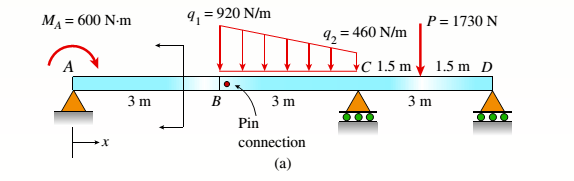
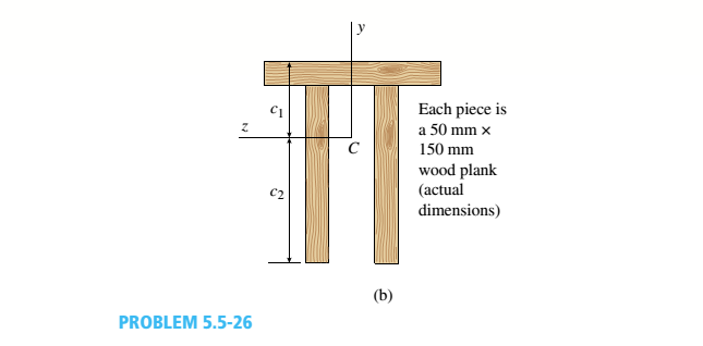
Consider the compound beam with segments AB and BCD joined by a pin connection (moment release) just right of B (see figure part a). The beam cross section is a double-T made up from three 50 mm × 150 mm wood members (actual dimensions, see figure part b),
(a) Find the cent raid C of the double-T cross section (c1:c2): then compute the moment of inertia, [I2 (mm4 )].
(b) Find the maximum tensile normal stress ifand maximum compressive normal stress tt. (kPa) for the loading shown. (Ignore the weight of the beam.)
(a)
The centroid
The moment of inertia of the section.
Answer to Problem 5.5.26P
The centroid
The moment of inertia of the section.
Explanation of Solution
Given information:
Width of the beam is
The following figure shows the distribution of forces on the beam
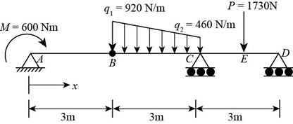
Figure-(1)
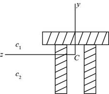
Figure-(2)
Write the expression for the distance of the centroid from the bottom.
Here, the for the distance of the centroid from the bottom is
Write the expression for the sum of centroids.
Here, the for the distance of the centroid from the top is
Write the expression for moment of inertia.
Here, the moment of inertia is
Calculation:
Substitute
Substitute
Substitute
Conclusion:
The centroid
The moment of inertia of the section
(b)
The maximum tensile normal stress.
The maximum compressive normal stress
Answer to Problem 5.5.26P
The maximum tensile normal stress is
The maximum compressive normal stress is
Explanation of Solution
The following figure shows the distribution of forces on the beam.
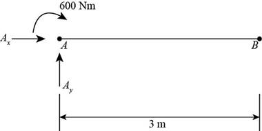
Figure-(3)
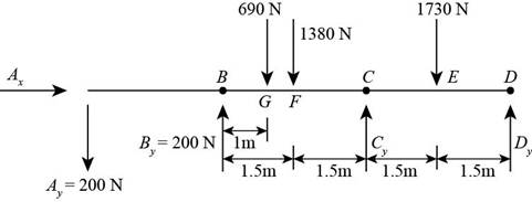
Figure-(4)
Write the expression for the moment about point
Here, the length of the member is
Write the expression for the vertical equilibrium of forces.
Here, the vertical reaction at point
Write the expression for moment at point
Here, the distance between the point
Write the expression for the vertical equilibrium of forces of free body
Here, the vertical reaction at point
Write the expression for the moment about point E
Here, the moment about point
Write the expression for the moment about point
Here, the moment about point
Write the expression for moment about point F
Here, the moment about point
Write the expression for moment about point
Here, the moment about point
Write the expression for moment about point
Here, the total moment about point
Write the expression for maximum tensile stress.
Here, the maximum tensile stress is
Calculation:
Substitute
Substitute
Substitute
Substitute
Substitute
Substitute
Substitute
Substitute
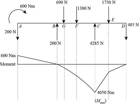
Figure-(5)
Substitute
Substitute
Conclusion:
The maximum tensile normal stress is
The maximum compressive normal stress is
Want to see more full solutions like this?
Chapter 5 Solutions
Bundle: Mechanics Of Materials, Loose-leaf Version, 9th + Mindtap Engineering, 1 Term (6 Months) Printed Access Card


- Bridges are usually modeled as simply supported beams. Your role in a building and construction company is to analyse and design the bridge based on simply supported beam theory. Your manager asked you to perform a stress analysis for bridge element modelled as simply supported beam shown in the Figure.1(a), this task is best achieved by performing the following required steps: 2 kN 3 kN/m 3 kN/m 3kN.m A 0.5 kN 4.5 kN kN 2 m 1 т+1m- 2 m R| -2 m (а) (b) Figure.1: (a) Bridge element modelled as simply supported beam (b) Beam sectionarrow_forwardThe figure below shows two solid homogenous rectangular beam sections with (breadth x depth) dimensions in two different orientations as follows: Beam Section Orientation A (t mm x 2t mm); and Beam Section Orientation B (2t mm x t mm). Both beams sag when subjected to the same loading and support conditions resulting in compressive stresses above the centroid line (neutral axis). Which statement accurately describes the relative maximum compressive stress (ocompression) between these beam section orientations? t mm 2t mm 2t mm t mm Beam Section Orientation A Beam Section Orientation B O a. Maximum compressive stress (ocompression) in orientation A is greater than orientation B by a factor of 4. O b. Maximum compressive stress (ocompression) in orientation B is greater than orientation A by a factor of 2. O c. Maximum compressive stress (ocompression) in orientation B is greater than orientation A by a factor of 4. O d. Maximum compressive stress (ocompression) in orientation A is…arrow_forwardI: The above figure (not drawn to scale) shows a rectangular beam with a depth of d = 34mm and breadth of b=90mm subjected to a combined loading of F= 10kN direct load and M = 100Nm bending load. The bending moment is acting about the depth of the beam (causing it to bend about its depth, d). Calculate the second moment of area, I, in m4 in the form a x 10- where the number a is correct to two decimal places. σp: x10 m4 σB: Calculate the direct stress, op, in megapascals (MPa) correct to two decimal places. MPa σ: d M Calculate the maximum bending stress, B, in megapascals (MPa) correct to two decimal places. MPa F MPa Hence, calculate the maximum resultant stress, a, due to the combined loading. Enter your answer in megapascals (MPa) correct to two decimal places:arrow_forward
- Q: For the cantilever beam with uniformly distributed load shown in Figure find;a The maximum shear force in the beam in (kN)b. The maximum bending moment in the beam in (kN.m)c. The area of the section in (mm2)d. The moment of inertia about the centroidal x axise. The maximum shear stress at section 1 in (MPa)g. The maximum shear stress at section 2 (within the flange) in (MPa)j. The maximum shear stress at section 2 (within the web) in (MPa)t. The maximum shear stress at section 3 (at the neutral axis) in (MPa)r. The average shear stress on the section (MPa)arrow_forwardQuestion 2. The figure below shows a hollow circular beam with an outside diameter of 250 mm and a wall thickness of 20 mm loaded in bending with force F = 50 kN. F Ra I: Young's modulus of the beam is 60 GPa.. Calculate the second moment of area, I, in m4 in the form ax 106 where the number a is correct to two decimal places. M: 1 m x 10 m4 Calculate the maximum bending moment, M, in kilonewtonmetres (kNm): σ: kNm E: 1 m Calculate the maximum bending stress, o, in megapascals (MPa) correct to two decimal places. Rb MPa Hence, calculate the maximum compressive strain, e, Enter your answer in micro-strain correct to two decimal places: micro-strain Type here to search 91 DELL 80°Farrow_forwardFind expressions for shear force V and moment M at x = L/2 of beam AB in structure (a). Express V and M in terms of peak load intensity go and beam length variable L. Repeat for structure (b) but find V and M at the mid-span of member BC. A A L/2 V. M at L/2 on AB L/2 [/2 B Structure (a) L/2 B 90 Structure (b) 90 V, Mat mid-span of BC 4L/5 4 4L/5 0000arrow_forward
- This question is made of two separate parts related to figures 1 and 2. 3 m a Figure 1 The support reaction at pin A along y-axis is The support reaction at roller B is 2 m in in B direction A| Figure 1 A beam AB is supported by a pin at A and a roller at B. The beam is subjected to force F of 450N, making an angle a-400 with horizontal as shown in figure 1. The support reaction at pin A along x-axis is to the direction L Figure 2 B 4 Figure 2 A beam AB of length L-1 m is supported by a pin at A and a cable BC at point B. The beam is subject to an external moment M-550 N.m at B as shown in figure 2. The force in cable BC is and it is in 3 С.arrow_forward3-In the figure given below, P(load) and M(moment) effects from the mid point of the fixed beam from both sides. Find the displacement and reaction forces.(Please use your own words. Marrow_forwardThis question is made of two separate parts related to figures 1 and 2. 3 m a Figure 1 2 m in in B direction A| direction L Figure 1 A beam AB is supported by a pin at A and a roller at B. The beam is subjected to force F of 450N, making an angle a-400 with horizontal as shown in figure 1. The support reaction at pin A along x-axis is to the The support reaction at pin A along y-axis is The support reaction at roller B is Figure 2 B 4 Figure 2 A beam AB of length L-1 m is supported by a pin at A and a cable BC at point B. The beam is subject to an external moment M-550 N.m at B as shown in figure 2. The force in cable BC is and it is in 3 с.arrow_forward
- The beam in the figure below is subjected to a load P = 3.5 kN at its end. Young’s modulus is 210 GPa and the moment of inertia for the beam’s cross-section is 5×106 mm4. If a = 1.5 m and b = 0.6 m, determine: a) Reaction value at support A. Positive direction is considered upwards. b) moment equation M(x1) in the segment AB, where x1 changes from 0 at support A to a at support B. Enter the equation in terms of variables P, a, band x1. c) moment equation M(x2) in the segment BC, where x2 changes from 0 at point C to b at support B. Enter the equation in terms of variables P, a, band x2. d) the value of the constant of integration C1 e) the value of the constant of integration C2 f) the value of the constant of integration C3 g) the value of the constant of integration C4 h) the value of displacement at point C i) the position of maximum displacement in the segment AB j) the value of maximum displacement in the segment ABarrow_forwardA thin beam with a solid rectangular cross-section is loaded as shown in Figure Q7 below. L/3 L/3 L/3 Figure Q7 Consider the following statoments and select which combination correctly describes the bending moment diagram for this beam, along its longth using the sign conventions provided in lectures. i lt is symmetrical. ii It has a value of zero at the mid-point. i. It has a negative value for the entire length of the beam. iv. It is described by a quadratic (2nd order) function. O ali and i. are both correct. Ob.li. and iv. are both correct. Oci. and i. are both correct. Od.i. and iv. are both correct. Oe. li. and iv. are both correct. O. None of the provided answers are correct. OBi and i. are both correct.arrow_forwardFigure Q2(b) shows the cross-section of a cantilever beam ABC. The beam is subjected to uniformly distributed loading and a concentrated force as shown in Figure Q2(c). Determine:(i) the second moment of area or moment of inertia for the cross-section about its neutral axis (NA)(ii) the internal bending moment and bending stress at section x-x as shown in Figure Q2(c) and at points P and Q of the cross section as shown in Figure Q2(b) of the beam and state whether the bending stress is in tension or compression.arrow_forward
 Elements Of ElectromagneticsMechanical EngineeringISBN:9780190698614Author:Sadiku, Matthew N. O.Publisher:Oxford University Press
 Mechanics of Materials (10th Edition)Mechanical EngineeringISBN:9780134319650Author:Russell C. HibbelerPublisher:PEARSON
 Thermodynamics: An Engineering ApproachMechanical EngineeringISBN:9781259822674Author:Yunus A. Cengel Dr., Michael A. BolesPublisher:McGraw-Hill Education
 Control Systems EngineeringMechanical EngineeringISBN:9781118170519Author:Norman S. NisePublisher:WILEY
 Mechanics of Materials (MindTap Course List)Mechanical EngineeringISBN:9781337093347Author:Barry J. Goodno, James M. GerePublisher:Cengage Learning
 Engineering Mechanics: StaticsMechanical EngineeringISBN:9781118807330Author:James L. Meriam, L. G. Kraige, J. N. BoltonPublisher:WILEY