Concept explainers
Videos
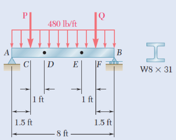
The beam AB supports a uniformly distributed load of 480 lb/ft and two concentrated loads P and Q. The normal stress due to bending on the bottom edge of the lower flange is +14.85 ksi at D and +10.65 ksi at E. (a) Draw the shear and bending-moment diagrams for the beam. (b) Determine the maximum normal stress due to bending that occurs in the beam.
Fig. P5.63
(a)
Draw the shear and bending-moment diagrams for the beam.
Explanation of Solution
Given information:
The normal stress due to bending at the point D is
The normal stress due to bending at the point E is
Refer to Appendix C “Properties of Rolled-Steel Sections” in the textbook.
The section modulus (S) for
Determine the bending moment at point D
Here, the normal stress at point D is
Substitute 14.85 ksi for
Determine the bending moment at point E
Here, the normal stress at point E is
Substitute 10.65 ksi for
Show the free-body diagram of the region DE as in Figure 1.
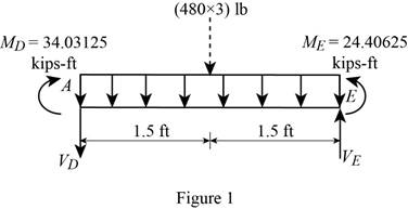
Determine the vertical reaction at point D by taking moment about point E.
Show the free body diagram of the region ACD as in Figure 2.
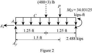
Determine the magnitude of the load P by taking moment about the point A.
Determine the vertical reaction at point A by resolving the vertical component of forces.
Show the free body diagram of the entire beam as in Figure 3.
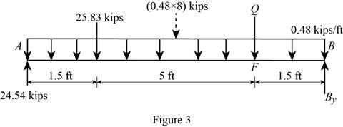
Determine the magnitude of the load P by taking moment about the point B.
Determine the vertical reaction at point A by resolving the vertical component of forces.
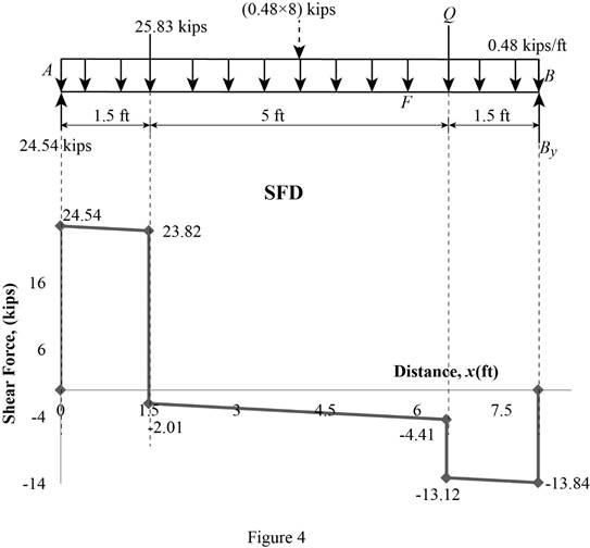
Shear force:
Show the calculation of shear force as follows;
Show the calculated shear force values as in Table 1.
| Location (x) ft | Shear force (V) kips |
| A | 24.54 |
| C (Left) | 23.82 |
| C (Right) | –2.01 |
| F (Left) | –4.41 |
| F (Right) | –13.12 |
| B | –13.84 |
Plot the shear force diagram as in Figure 4.
Bending moment:
Show the calculation of the bending moment as follows;
Show the calculated bending moment values as in Table 2.
| Location (x) ft | Bending moment (M) kips-ft |
| A | 0 |
| C | 36.27 |
| F | 19.77 |
| B | 0 |
Plot the bending moment diagram as in Figure 5.
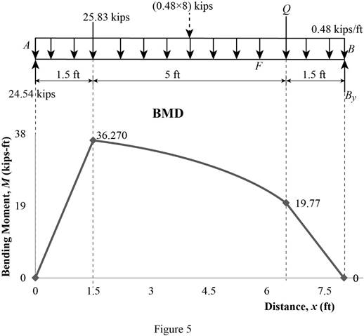
Refer to Figure 5;
The maximum absolute bending moment is
(b)
The maximum normal stress due to bending.
Answer to Problem 63P
The maximum normal stress due to bending is
Explanation of Solution
Given information:
Refer to Appendix C “Properties of Rolled-Steel Sections” in the textbook.
The section modulus (S) for
The maximum absolute bending moment is
Determine the maximum normal stress
Substitute
Therefore, the maximum normal stress due to bending is
Want to see more full solutions like this?
Chapter 5 Solutions
Mechanics of Materials 7th Edition


- A 12-m simply supported overhang beam is supported at x = 0 and x = 10m. The overhanging portion is from x = 10m to x = 12m (the overhang portion is 2m). Two equal wheel loads of 20kN each, separated by 2m roll as a unit across the 12-m span. Determine the maximum shear developed in the span.arrow_forwardTwo small channel sections DF and EH have been welded to the uniform beam AB of weight W = 3 kN to form the rigid structural member shown. This member is being lifted by two cables attached at D and E . Knowing that 0= 30° and neglecting the weight of the channel sections, (a) draw the shear and bending-moment diagrams for beam AB, (b) determine the maximum absolute values of the shear and bending moment in the beam.arrow_forwardDetermine (a) the equations of the shear and bending-moment curves for the beam and loading shown, (b) the maximum absolute value of the bending moment in the beamarrow_forward
- Determine (a) the distance a for which the maximum absolute value of the bending moment in the beam is as small as possible, (b) the corresponding maximum normal stress due to bending.arrow_forwardThe maximum bending stress of a hollow shaft is equivalent to 80N/mm2, while the maximum shear stress is equal to 70 N/mm2.The shaft rotates and loads are applied suddenly, with minor shocks. Determine the outer and inner diameter (in mm) of a hollow shaft that is required to carry a bending moment of 2100 N-m and a torque of 4100 N-m if the thickness of the hollow shaftis equal to 0.15of the outer diameter of the shaft. Apply ASME Code for this problem.arrow_forwardA timber beam AB of length L and rectangular cross section carries a single concentrated load P at its midpoint C. (a) Show that the ratio Tm/ m of the maximum values of the shearing and normal stresses in the beam is equal to h/2L, where h and L are, respectively, the depth and the length of the beam. (b) Determine the depth h and the width b of the beam, knowing that L = 2 m, P = 40 kN, 7m = 960 kPa, and om = 12 MPa.arrow_forward
- Knowing the vertical reaction at the roller support at C of the beam shown is 12.5 kN upward, determine the requested algebraic expressions for shear and moment (in terms of the variable x), using the proper sign conventions established for drawing the shear and bending moment diagrams. (a) The shear and moment equations (in terms of the variable x) for the left region of the beam between points A and B, using the F.B.D. of the left-side of your considered cut section (b) The shear and moment equations (in terms of the variable x) for the right region of the beam between points B and C using the F.B.D. of the right-side of your considered cut section.please show all steps and FBD.arrow_forwardDetermine (a) the equations of the shear and bending moment curves for the beam and loading shown, (b) the maximum absolute value of the bending moment in the beam.arrow_forwardA weightlifting bar is loaded symmetrically in A and D (P = 1500N of each side). The weightlifter's hands are located at B and C, 0.45 m from A and D. Determine the maximum bending moment in the bar ABCD and the minimum diameter d of the bar knowing that the constraint admissible for the material of the bar is 200MPa.arrow_forward
- The maximum normal bending stress in a beam, Mc/I, occurs along the beam where the bending moment isarrow_forwardKnowing that P= 480 N,Q=320N determine (a) the distance a for which the absolute value of the bending moment in the beam is as small as possible, (b) the corresponding maximum normal stress due to bending.arrow_forwardKnowing that P=Q= 480 N, determine (a) the distance a for which the absolute value of the bending moment in the beam is as small as possible, (b) the corresponding maximum normal stress due to bending.arrow_forward
 Elements Of ElectromagneticsMechanical EngineeringISBN:9780190698614Author:Sadiku, Matthew N. O.Publisher:Oxford University Press
 Mechanics of Materials (10th Edition)Mechanical EngineeringISBN:9780134319650Author:Russell C. HibbelerPublisher:PEARSON
 Thermodynamics: An Engineering ApproachMechanical EngineeringISBN:9781259822674Author:Yunus A. Cengel Dr., Michael A. BolesPublisher:McGraw-Hill Education
 Control Systems EngineeringMechanical EngineeringISBN:9781118170519Author:Norman S. NisePublisher:WILEY
 Mechanics of Materials (MindTap Course List)Mechanical EngineeringISBN:9781337093347Author:Barry J. Goodno, James M. GerePublisher:Cengage Learning
 Engineering Mechanics: StaticsMechanical EngineeringISBN:9781118807330Author:James L. Meriam, L. G. Kraige, J. N. BoltonPublisher:WILEY