Mechanics of Materials 7th Edition
7th Edition
ISBN: 9780077625238
Author: BEER
Publisher: MCG
expand_more
expand_more
format_list_bulleted
Concept explainers
Videos
Textbook Question
Chapter 5.4, Problem 116P
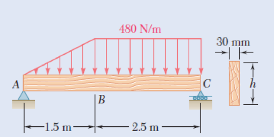
5.116 and 5.117 A timber beam is being designed to be supported and loaded as shown. (a) Using singularity functions, find the magnitude and location of the maximum bending moment in the beam. (b) Knowing that the available stock consists of beams with an allowable normal stress of 12 MPa and a rectangular cross section of 30-mm width and depth h varying from 80 mm to 160 mm in 10-mm increments, determine the most economical cross section that can be used.
Fig. P5.116
Expert Solution & Answer
Want to see the full answer?
Check out a sample textbook solution
Students have asked these similar questions
Determine (a) the distance a for which the maximum absolute value of the bending moment in the beam is as small as possible, (b) the corresponding maximum normal stress due to bending.
The rectangular tube shown is extruded from an aluminum alloy for which σY= 40 ksi, σU= 60 ksi, and E= 10.6 * 106 psi. Neglecting the effect of fillets, determine (a) the bending moment M for which the factor of safety will be 3.00 and (b) the corresponding radius of curvature of the tube
Determine (a) the distance a for which the absolute value of the bending moment in the beam is as small as possible, (b) the corresponding moximum normal stress due to bending.
Chapter 5 Solutions
Mechanics of Materials 7th Edition
Ch. 5.1 - 5.1 through 5.6 For the beam and loading shown,...Ch. 5.1 - 5.1 through 5.6 For the beam and loading shown,...Ch. 5.1 - 5.1 through 5.6 For the beam and loading shown,...Ch. 5.1 - 5.1 through 5.6 For the beam and loading shown,...Ch. 5.1 - 5.1 through 5.6 For the beam and loading shown,...Ch. 5.1 - 5.1 through 5.6 For the beam and loading shown,...Ch. 5.1 - 5.7 and 5.8 Draw the shear and bending-moment...Ch. 5.1 - 5.7 and 5.8 Draw the shear and bending-moment...Ch. 5.1 - 5.9 and 5.10 Draw the shear and bending-moment...Ch. 5.1 - 5.9 and 5.10 Draw the shear and bending-moment...
Ch. 5.1 - 5.11 and 5.12 Draw the shear and bending-moment...Ch. 5.1 - 5.11 and 5.12 Draw the shear and bending-moment...Ch. 5.1 - 5.13 and 5.14 Assuming that the reaction of the...Ch. 5.1 - 5.13 and 5.14 Assuming that the reaction of the...Ch. 5.1 - 5.15 and 5.16 For the beam and loading shown,...Ch. 5.1 - 5.15 and 5.16 For the beam and loading shown,...Ch. 5.1 - For the beam and loading shown, determine the...Ch. 5.1 - For the beam and loading shown, determine the...Ch. 5.1 - 5.19 and 5.20 For the beam and loading shown,...Ch. 5.1 - 5.19 and 5.20 For the beam and loading shown,...Ch. 5.1 - Draw the shear and bending-moment diagrams for the...Ch. 5.1 - 5.22 and 5.23 Draw the shear and bending-moment...Ch. 5.1 - 5.22 and 5.23 Draw the shear and bending-moment...Ch. 5.1 - 5.24 and 5.25 Draw the shear and bending-moment...Ch. 5.1 - 5.24 and 5.25 Draw the shear and bending-moment...Ch. 5.1 - Knowing that W = 12 kN, draw the shear and...Ch. 5.1 - Determine (a) the magnitude of the counterweight W...Ch. 5.1 - Determine (a) the distance a for which the...Ch. 5.1 - Knowing that P = Q = 480 N, determine (a) the...Ch. 5.1 - Solve Prob. 5.29, assuming that P = 480 N and Q =...Ch. 5.1 - Determine (a) the distance a for which the...Ch. 5.1 - A solid steel rod of diameter d is supported as...Ch. 5.1 - A solid steel bar has a square cross section of...Ch. 5.2 - Using the method of Sec. 5.2, solve Prob. 5.1a....Ch. 5.2 - Using the method of Sec. 5.2, solve Prob. 5.2a....Ch. 5.2 - Prob. 36PCh. 5.2 - Prob. 37PCh. 5.2 - Using the method of Sec. 5.2, solve Prob. 5.5a....Ch. 5.2 - Using the method of Sec. 5.2, solve Prob. 5.6a....Ch. 5.2 - Using the method of Sec. 5.2, solve Prob. 5.7. 5.7...Ch. 5.2 - Using the method of Sec. 5.2, solve Prob. 5.8. 5.7...Ch. 5.2 - Prob. 42PCh. 5.2 - Using the method of Sec. 5.2, solve Prob. 5.10....Ch. 5.2 - 5.44 and 5.45 Draw the shear and bending-moment...Ch. 5.2 - 5.44 and 5.45 Draw the shear and bending-moment...Ch. 5.2 - Prob. 46PCh. 5.2 - Prob. 47PCh. 5.2 - Prob. 48PCh. 5.2 - Using the method of Sec. 5.2, solve Prob. 5.20....Ch. 5.2 - 5.50 and 5.51 Determine (a) the equations of the...Ch. 5.2 - 5.50 and 5.51 Determine (a) the equations of the...Ch. 5.2 - 5.52 and 5.53 Determine (a) the equations of the...Ch. 5.2 - 5.52 and 5.53 Determine (a) the equations of the...Ch. 5.2 - 5.54 and 5.55 Draw the shear and bending-moment...Ch. 5.2 - 5.54 and 5.55 Draw the shear and bending-moment...Ch. 5.2 - 5.56 and 5.57 Draw the shear and bending-moment...Ch. 5.2 - 5.56 and 5.57 Draw the shear and bending-moment...Ch. 5.2 - 5.58 and 5.59 Draw the shear and bending-moment...Ch. 5.2 - 5.58 and 5.59 Draw the shear and bending-moment...Ch. 5.2 - Knowing that beam AB is in equilibrium under the...Ch. 5.2 - Knowing that beam AB is in equilibrium under the...Ch. 5.2 - The beam AB supports two concentrated loads P and...Ch. 5.2 - The beam AB supports a uniformly distributed load...Ch. 5.2 - Beam AB supports a uniformly distributed load of 2...Ch. 5.3 - 5.65 and 5.66 For the beam and loading shown,...Ch. 5.3 - 5.65 and 5.66 For the beam and loading shown,...Ch. 5.3 - 5.67 and 5.68 For the beam and loading shown,...Ch. 5.3 - 5.67 and 5.68 For the beam and loading shown,...Ch. 5.3 - 5.69 and 5.70 For the beam and loading shown,...Ch. 5.3 - 5.69 and 5.70 For the beam and loading shown,...Ch. 5.3 - 5.71 and 5.72 Knowing that the allowable normal...Ch. 5.3 - 5.71 and 5.72 Knowing that the allowable normal...Ch. 5.3 - 5.73 and 5.74 Knowing that the allowable normal...Ch. 5.3 - 5.73 and 5.74 Knowing that the allowable normal...Ch. 5.3 - 5.75 and 5.76 Knowing that the allowable normal...Ch. 5.3 - 5.75 and 5.76 Knowing that the allowable normal...Ch. 5.3 - 5.77 and 5.78 Knowing that the allowable normal...Ch. 5.3 - 5.77 and 5.78 Knowing that the allowable normal...Ch. 5.3 - A steel pipe of 100-mm diameter is to support the...Ch. 5.3 - Two metric rolled-steel channels are to be welded...Ch. 5.3 - Two rolled-steel channels are to be welded back to...Ch. 5.3 - Two L4 3 rolled-steel angles are bolted together...Ch. 5.3 - Assuming the upward reaction of the ground to be...Ch. 5.3 - Assuming the upward reaction of the ground to be...Ch. 5.3 - Determine the largest permissible distributed load...Ch. 5.3 - Solve Prob. 5.85, assuming that the cross section...Ch. 5.3 - Determine the largest permissible value of P for...Ch. 5.3 - Solve Prob. 5.87, assuming that the T-shaped beam...Ch. 5.3 - Beams AB, BC, and CD have the cross section shown...Ch. 5.3 - Beams AB, BC, and CD have the cross section shown...Ch. 5.3 - Each of the three rolled-steel beams shown...Ch. 5.3 - A 54-kip load is to be supported at the center of...Ch. 5.3 - A uniformly distributed load of 66 kN/m is to be...Ch. 5.3 - A roof structure consists of plywood and roofing...Ch. 5.3 - Solve Prob. 5.94, assuming that the 6-kN...Ch. 5.3 - Prob. 96PCh. 5.3 - Assuming that the front and rear axle loads remain...Ch. 5.4 - 5.98 through 5.100 (a) Using singularity...Ch. 5.4 - 5.98 through 5.100 (a) Using singularity...Ch. 5.4 - 5.98 through 5.100 (a) Using singularity...Ch. 5.4 - 5.101 through 5.103 (a) Using singularity...Ch. 5.4 - Prob. 102PCh. 5.4 - Prob. 103PCh. 5.4 - Prob. 104PCh. 5.4 - Prob. 105PCh. 5.4 - Prob. 106PCh. 5.4 - Prob. 107PCh. 5.4 - Prob. 108PCh. 5.4 - Prob. 109PCh. 5.4 - Prob. 110PCh. 5.4 - Prob. 111PCh. 5.4 - Prob. 112PCh. 5.4 - 5.112 and 5.113 (a) Using singularity functions,...Ch. 5.4 - Prob. 114PCh. 5.4 - 5.114 and 5.115 A beam is being designed to be...Ch. 5.4 - 5.116 and 5.117 A timber beam is being designed to...Ch. 5.4 - Prob. 117PCh. 5.4 - Prob. 118PCh. 5.4 - Prob. 119PCh. 5.4 - 5.118 through 5.121 Using a computer and step...Ch. 5.4 - Prob. 121PCh. 5.4 - 5.122 and 5.123 For the beam and loading shown and...Ch. 5.4 - 5.122 and 5.123 For the beam and loading shown and...Ch. 5.4 - 5.124 and 5.125 For the beam and loading shown and...Ch. 5.4 - Prob. 125PCh. 5.5 - 5.126 and 5.127 The beam AB, consisting of a...Ch. 5.5 - Prob. 127PCh. 5.5 - 5.128 and 5.129 The beam AB, consisting of a...Ch. 5.5 - 5.128 and 5.129 The beam AB, consisting of a...Ch. 5.5 - Prob. 130PCh. 5.5 - Prob. 131PCh. 5.5 - Prob. 132PCh. 5.5 - 5.132 and 5.133 A preliminary design on the use of...Ch. 5.5 - Prob. 134PCh. 5.5 - Prob. 135PCh. 5.5 - Prob. 136PCh. 5.5 - Prob. 137PCh. 5.5 - Prob. 138PCh. 5.5 - Prob. 139PCh. 5.5 - Assuming that the length and width of the cover...Ch. 5.5 - Two cover plates, each 12 in. thick, are welded to...Ch. 5.5 - Two cover plates, each 12 in. thick, are welded to...Ch. 5.5 - Prob. 143PCh. 5.5 - Prob. 144PCh. 5.5 - Two cover plates, each 7.5 mm thick, are welded to...Ch. 5.5 - Prob. 146PCh. 5.5 - Prob. 147PCh. 5.5 - For the tapered beam shown, determine (a) the...Ch. 5.5 - Prob. 149PCh. 5.5 - Prob. 150PCh. 5.5 - Prob. 151PCh. 5 - Draw the shear and bending-moment diagrams for the...Ch. 5 - Draw the shear and bending-moment diagrams for the...Ch. 5 - Determine (a) the distance a for which the...Ch. 5 - For the beam and loading shown, determine the...Ch. 5 - Draw the shear and bending-moment diagrams for the...Ch. 5 - Beam AB, of length L and square cross section of...Ch. 5 - Prob. 158RPCh. 5 - Knowing that the allowable normal stress for the...Ch. 5 - Prob. 160RPCh. 5 - (a) Using singularity functions, find the...Ch. 5 - Prob. 162RPCh. 5 - Prob. 163RP
Knowledge Booster


Learn more about
Need a deep-dive on the concept behind this application? Look no further. Learn more about this topic, mechanical-engineering and related others by exploring similar questions and additional content below.Similar questions
- Five metal strips, each of 0.5 * 1.5-in. cross section, are bonded together to form the composite beam shown. The modulus of elasticity is 30* 106 psi for the steel, 15 *106 psi for the brass, 10 *106 psi for the aluminum. Knowing that the beam is bent about a horizontal axis by a couple of moment 12 kip·in., determine (a) the maximum stress in each of the three metals, (b) the radius of curvature of the composite beam.arrow_forwardA) The four cross sections shown have different characteristics when subjected to a vertical shear force. Which of the four geometries shown has the largest value for the moment of the area, Q, about the neutral axis? B) Which of the four geometries shown has the smallest value for its moment of inertia about the x axis? C) Given that all four geometries are subjected to the same vertical shear force V, which of the four has the smallest value for the maximum shear stress?arrow_forwardA solid steel rod of diameter d is supported as shown. Knowing that for steel γ= 490 lb/ft3, determine the smallest diameter d that can be used if the normal stress due to bending is not to exceed 4 ksiarrow_forward
- Knowing that a beam of the cross section shown is bent about a hori-zontal axis and that the bending moment is 50 kip-in., determine the total force acting (a) on the top flange (b) on the shaded portion of the webarrow_forwardFor the beam and loading shown, design the cross section of the beam knowing that the grade of timber used has an allowable normal stress of 12 MPa.arrow_forwardTwo small channel sections DF and EH have been welded to the uniform beam AB of weight W = 3 kN to form the rigid structural member shown. This member is being lifted by two cables attached at D and E . Knowing that 0= 30° and neglecting the weight of the channel sections, (a) draw the shear and bending-moment diagrams for beam AB, (b) determine the maximum absolute values of the shear and bending moment in the beam.arrow_forward
- A beam consists of three planks connected by steel bolts with a lon-gitudinal spacing of 225 mm. Knowing that the shear in the beam is vertical and equal to 6 kN and that the allowable average shearing stress in each bolt is 60 MPa, determine the smallest permissible bolt diameter that can be usedarrow_forwardFor the beam and loading shown, determine the equations of the shear and bending-moment curves and the maximum absolute value of the bending moment in the beam, knowing that (a) k= 1, (b) k= 0.5.arrow_forwardKnowing that the allowable normal stress for the steel used is 24 ksi, select the most economical wide-flange beam to support the loading shownarrow_forward
- Determine the maximum load F that can be applied at the free end of a 3 m cantilever beam of universal rolled-steel beam cross-section, 356 mm deep, with a moment of inertia of 142 × 106 mm4, if the allowable stress is 76 MPa.arrow_forwardKnowing that the allowable normal stress for the steel used is 160 MPa, select the most economical wide-flange beam to support the loading shown.arrow_forwardFor the beam and loading shown, consider section n–n and determine the shearing stress at (a) point a, (b) point b.arrow_forward
arrow_back_ios
SEE MORE QUESTIONS
arrow_forward_ios
Recommended textbooks for you
 Elements Of ElectromagneticsMechanical EngineeringISBN:9780190698614Author:Sadiku, Matthew N. O.Publisher:Oxford University Press
 Mechanics of Materials (10th Edition)Mechanical EngineeringISBN:9780134319650Author:Russell C. HibbelerPublisher:PEARSON
 Thermodynamics: An Engineering ApproachMechanical EngineeringISBN:9781259822674Author:Yunus A. Cengel Dr., Michael A. BolesPublisher:McGraw-Hill Education
 Control Systems EngineeringMechanical EngineeringISBN:9781118170519Author:Norman S. NisePublisher:WILEY
 Mechanics of Materials (MindTap Course List)Mechanical EngineeringISBN:9781337093347Author:Barry J. Goodno, James M. GerePublisher:Cengage Learning
 Engineering Mechanics: StaticsMechanical EngineeringISBN:9781118807330Author:James L. Meriam, L. G. Kraige, J. N. BoltonPublisher:WILEY
Elements Of Electromagnetics
Mechanical Engineering
ISBN:9780190698614
Author:Sadiku, Matthew N. O.
Publisher:Oxford University Press
Mechanics of Materials (10th Edition)
Mechanical Engineering
ISBN:9780134319650
Author:Russell C. Hibbeler
Publisher:PEARSON
Thermodynamics: An Engineering Approach
Mechanical Engineering
ISBN:9781259822674
Author:Yunus A. Cengel Dr., Michael A. Boles
Publisher:McGraw-Hill Education
Control Systems Engineering
Mechanical Engineering
ISBN:9781118170519
Author:Norman S. Nise
Publisher:WILEY
Mechanics of Materials (MindTap Course List)
Mechanical Engineering
ISBN:9781337093347
Author:Barry J. Goodno, James M. Gere
Publisher:Cengage Learning
Engineering Mechanics: Statics
Mechanical Engineering
ISBN:9781118807330
Author:James L. Meriam, L. G. Kraige, J. N. Bolton
Publisher:WILEY
Everything About COMBINED LOADING in 10 Minutes! Mechanics of Materials; Author: Less Boring Lectures;https://www.youtube.com/watch?v=N-PlI900hSg;License: Standard youtube license