
Concept explainers
Videos
Assuming that the front and rear axle loads remain in the same ratio as for the truck of Prob. 5.96, determine how much heavier a truck could safely cross the bridge designed in that problem.
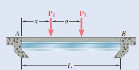
5.96 A bridge of length L = 48 ft is to be built on a secondary road whose access to trucks is limited to two-axle vehicles of medium weight. It will consist of a concrete slab and of simply supported steel beams with an ultimate strength σU = 60 ksi. The combined weight of the slab and beams can be approximated by a uniformly distributed load w = 0.75 kips/ft on each beam. For the purpose of the design, it is assumed that a truck with axles located at a distance a = 14 ft from each other will be driven across the bridge and that the resulting concentrated loads P1 and P2 exerted on each beam could be as large as 24 kips and 6 kips, respectively. Determine the most economical wide-flange shape for the beams, using LRFD with the load factors γD = 1.25, γL = 1.75 and the resistance factor ϕ = 0.9. [Hint: It can be shown that the maximum value of |ML| occurs under the larger load when that load is located to the left of the center of the beam at a distance equal to aP2/2(P1 + P2).]
Fig. P5.96
Want to see the full answer?
Check out a sample textbook solution
Chapter 5 Solutions
Mechanics of Materials, 7th Edition


- Determine the sag of a 30-ft chain that is attached to two points at the same elevation that are 20 ft apart.arrow_forwardThree bars, two made of aluminum and one made of steel, support a rigid block. An object of weight W is dropped vertically from a distance h above the rigid block. Both steel and aluminum bars have cross-sectional area of 50 mm2 and length of 0.5 m. The elastic moduli for the aluminum and steel are 76 GPa and 184 GPa, respectively. a) If W=1000N and h=0.1m, determine whether the three bars are still safe to perform. b) If h=0.2m, determine the maximum weight that can be dropped without causing failure to the barsarrow_forwardKnowing that the average normal stress in member CE of the Pratt bridge truss shown must not exceed 21 ksi for the given loading,determine the cross-sectional area of that member that will yield the most economical and safe design. Assume that both ends of the member will be adequately reinforcedarrow_forward
- A large number of uniform and identical cantilever beams, each 1 m long and 146 N / m in weight, are used to support pipes. Consider that the length of the tubes acting under a typical ABCD beam is 1.2 m. And that tubes B and C, plus their contents, weigh 365 N / m and 510 N / m, respectively, determine the reactions at the end set in A, of the cantilever beams.arrow_forwardThree loads are applied as shown to a light beam supported by cables attached at B and D. Neglecting the weight of the beam, determine the range of values of Q for which neither cable becomes slack when P=0.arrow_forwardFor the steel truss and loading shown, determine the magnitude of the force (lb) of member BD, knowing that x = 14.1 ft, y = 7.6 ft, and P = 22538 lb. Round off only on the final answer expressed in 3 decimal places .arrow_forward
- The 24-ft timber floor joist is designed to carry a uniformly distributed load. Because only 16-ft timbers are available, the joist is to be fabricated from two pieces connected by a nailed joint D. Determine the distance b for the most advantageous position of the joint D, knowing that nailed joints are strong in shear but weak in bending.arrow_forwardHelp me i need solve this _II_ A steel plate 10 mm thick is embedded in a horizontal concrete slab and is used to anchor high strength vertical cable as shown. The diameter of the hole in the plate is 24 mm. the ultimate strength of the steel used is 250 MPa. and the ultimate bonding stress between plate and concrete is 2.1 MPa. Knowing that a factor of safety of 3.60 is desired when P = 18 kN. Determine: a) the required width a of the plate. b) the minimum depth bb to which a plate of that width should be embedded in the concrete slab. (Neglect the normal stresses between the concrete and the lower end of the plate.)arrow_forwardA vibration isolation unit consists of two blocks of hard rubber with a modulus of rigidity G= 19 MPa bonded to a plate AB and to rigid supports as shown. Denoting by P the magnitude of the force applied to the plate and by δ the corresponding deflection, determine the effective spring constant, k 5 P/δ, of the system.arrow_forward
- Straight rods of 0.30-in. diameter and 200-ft length are sometimes used to clear underground conduits of obstructions or to thread wires through a new conduit. The rods are made of high-strength steel and, for storage and transportation, are wrapped on spools of 5-ft diameter. Assuming that the yield strength is not exceeded, determine (a) the maximum stress in a rod, when the rod, which was initially straight, is wrapped on the spool, (b) the corresponding bending moment in the rod. Use E= 29 * 106 psi.arrow_forwardA load P is supported as shown by a steel pin that has been inserted in a short wooden member hanging from the ceiling. The ultimate strength of the wood used is 60 MPa in tension and 7.5 MPa in shear,while the ultimate strength of the steel is 145 MPa in shear. Knowing that b = 40 mm, c = 55 mm, and d = 12 mm, determine the load P if an overall factor of safety of 3.2 is desired.arrow_forwardThe length of the 332332 -in.-diameter steel wire CD has been adjusted so that with no load applied, a gap of 116116 in. exists between the end B of the rigid beam ACB and contact point E. Knowing that E = 29 × 106 psi, determine where a 57-lb (w) block should be placed on the beam in order to cause contact between B and E. For contact, x < in.arrow_forward
 International Edition---engineering Mechanics: St...Mechanical EngineeringISBN:9781305501607Author:Andrew Pytel And Jaan KiusalaasPublisher:CENGAGE L